
Flapping wing mechanism

A technology of fixing the mounting plate and rotating plate, which is applied in the field of flapping wings, can solve the problem of insufficient stability of the long-term motion mechanism, and achieve the effects of stable mechanism, quality assurance, and small size

Pending Publication Date: 2021-08-10
郑法贵
View PDF0 Cites 0 Cited by
  • Summary
  • Abstract
  • Description
  • Claims
  • Application Information

AI Technical Summary

Problems solved by technology

[0003] There are few flapping wings with a certain weight driven by small power motors in some existing flapping wing mechanisms, and there are not many mechanisms in the small devices that can expand the flapping wings on both sides to 0-180 degrees, and the long-term motion mechanism is not stable enough

Method used


Image

  • Flapping wing mechanism
  • Flapping wing mechanism
  • Flapping wing mechanism

Examples


Embodiment Construction

[0024] The present invention will be further described below in conjunction with the accompanying drawings and embodiments.

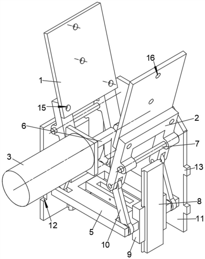
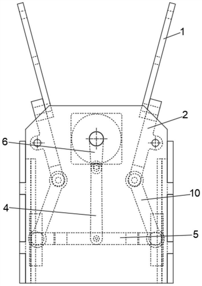
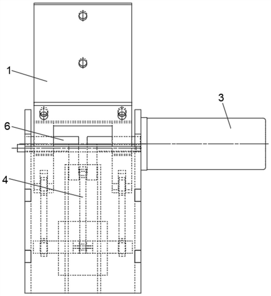
[0025] Please refer to figure 1 , figure 2 , image 3 , Figure 4 and Figure 5 ,in, figure 1 A structural schematic diagram of a preferred embodiment of the flapping wing mechanism provided by the present invention; figure 2 for figure 1 The schematic diagram of the front view structure is shown; image 3 for figure 1 The schematic diagram of the side view structure is shown; Figure 4 It is a schematic diagram of the state of the flapping wing rotating plate at the highest point of the crankshaft movement; Figure 5 It is a schematic diagram of the state of the flapping wing rotating plate at the lowest point of the crankshaft motion. Including: flapping wing fixed plate 1, flapping wing rotating plate 2, motor 3, pull rod 4, movable bottom plate 5, crankshaft 6, rotating shaft 7, guide rail 8, slider 9, linkage rod 10, fixed mounting plat...


PUM


Abstract

The invention provides a flapping wing mechanism. Four fixed mounting plates form a frame shaped like a Chinese character 'hui ', two rotating shafts which are symmetrically arranged are fixedly mounted on the two fixed mounting plates close to the front end and the rear end, flapping wing rotating plates are rotationally connected to the two rotating shafts, and flapping wing fixing plates are fixedly mounted at the upper ends of the two flapping wing rotating plates; a motor is mounted on the outer side wall of the fixed mounting plate located at the front end, a crankshaft is mounted on the inner side of the fixed mounting plate located at the front end, one end of the crankshaft is fixedly connected with the output end of the motor through a coupler, and the crankshaft is in transmission connection with the two flapping wing rotating plates through a limiting assembly. The flapping wing mechanism provided by the invention is small in size, and can solve the problem of placement and accommodation when the specific shape of a flapping wing bionic animal is manufactured; the small motor drives the heavier flapping wing, so that a large flapping wing bionic animal can be made; the mechanism is stable, and the quality of flapping wing products can be guaranteed; the unfolding angle can reach 0-180 degrees, and the movement characteristics of bionic flapping-wing animals are better met.

Description

technical field [0001] The invention relates to the field of flapping wings, in particular to a flapping wing mechanism. Background technique [0002] Another name for butterfly, which belongs to Arthropoda, Insecta, Lepidoptera, and Hammercera. There are more than 14,000 species in the world, most of which are distributed in the Americas, especially in the Amazon River Basin. The current flapping wing mainly refers to the flapping wings of animals with wings. Bionics is a scientific method to build technical systems by imitating the functions and behaviors of biological systems. It breaks the boundary between organisms and machines, and communicates various systems. In order to imitate the wings of animals, some existing bionics use machinery to imitate the flapping of animal wings to study the trajectory of animal flapping wings. [0003] There are few flapping wings with a certain weight driven by low-power motors in some existing flapping wing mechanism devices, and th...

Claims


Application Information

Patent Timeline
Patent Type & Authority Applications(China)
IPC IPC(8): B64C33/02
CPCB64C33/02
Inventor 郑法贵
Owner 郑法贵
Learn More