Experiment tank and transmission mechanism

A technology of transmission mechanism and drive components, applied in transmission devices, laboratory utensils, laboratory containers, etc., can solve the problems of cumbersome structure, long processing cycle, large transmission ratio and noise, etc.

Pending Publication Date: 2021-08-10
SHANXI YANG MEI CHEM IND MACHINERY
View PDF0 Cites 0 Cited by
  • Summary
  • Abstract
  • Description
  • Claims
  • Application Information

AI Technical Summary

Problems solved by technology

[0002] Turbine and worm is a common mechanical mechanism that transmits rotational motion between two vertically interlaced axes in space. It is characterized by large transmission ratio and low noise, but it also has disadvantages such...

Method used


Image

  • Experiment tank and transmission mechanism
  • Experiment tank and transmission mechanism
  • Experiment tank and transmission mechanism

Examples


Embodiment Construction

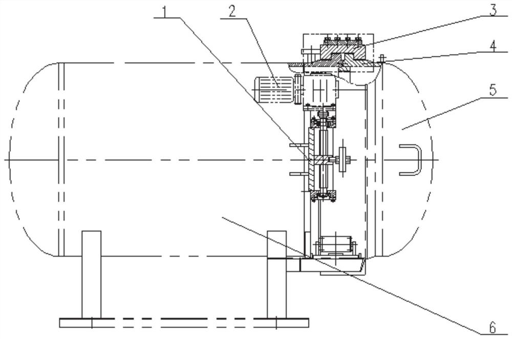
[0024] The present application provides a transmission mechanism, which simplifies the structure of the vertically intersecting axis transmission mechanism. The present application also provides an experimental tank comprising the above-mentioned transmission mechanism.

[0025] The technical solutions in the embodiments of the present application will be clearly and completely described below in conjunction with the accompanying drawings in the embodiments of the present application. Obviously, the described embodiments are only some of the embodiments of the present application, not all of them. Based on the embodiments of the present application, all other embodiments obtained by persons of ordinary skill in the art without making creative efforts belong to the protection scope of the present application.

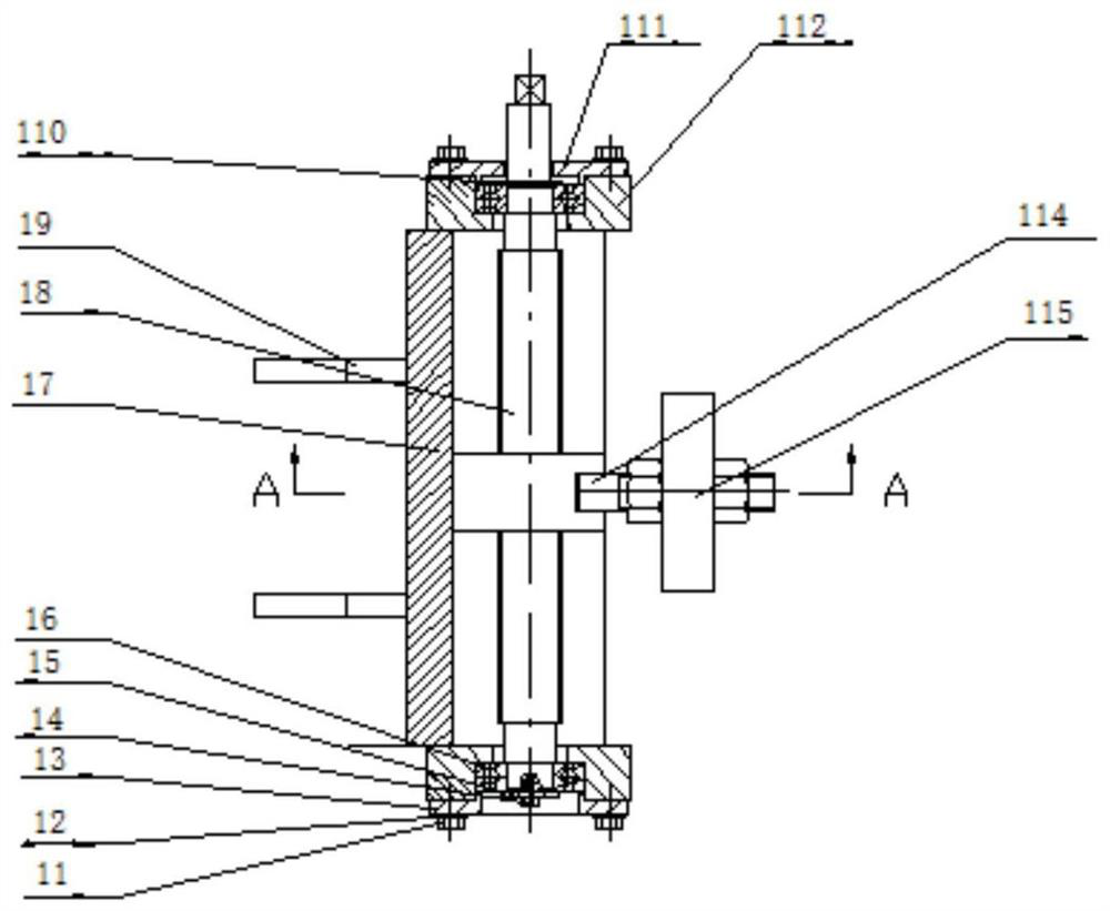
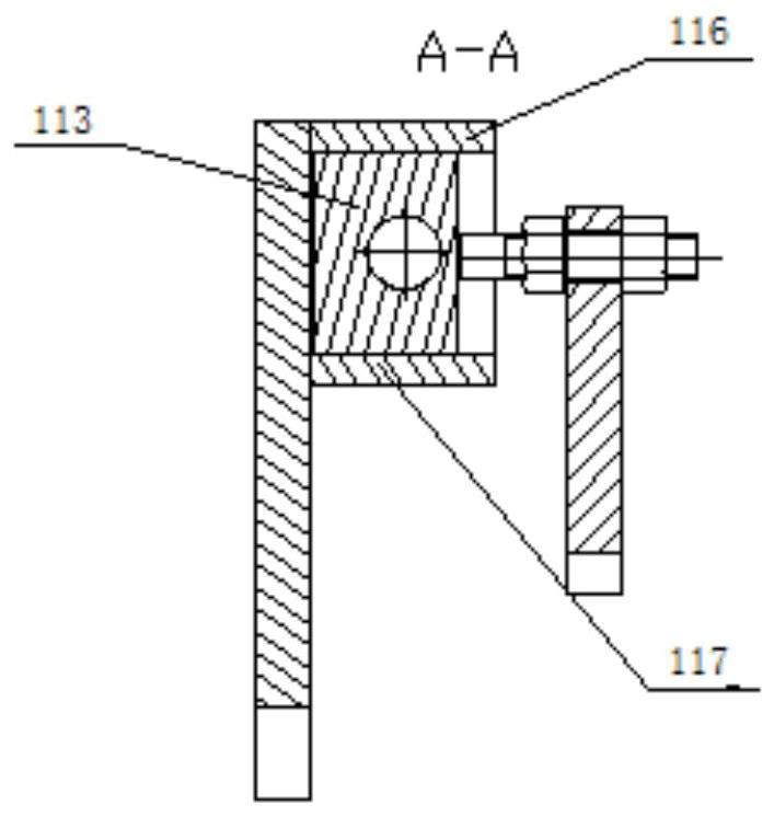
[0026] figure 1 A side sectional view of the transmission mechanism provided by this application; figure 2 AA sectional view of the transmission mechanism provided by...


PUM


Abstract

The invention provides a transmission mechanism. The transmission mechanism comprises a frame body, a lead screw, a driving part, a nut block and a connecting plate. The lead screw is vertically arranged on the frame body, and the two ends of the lead screw are rotationally connected with the frame body. The driving part is connected with the lead screw and used for driving the lead screw to rotate. The nut block is in threaded connection with threads of the lead screw, a connecting groove with two closed ends is formed in the side direction of the nut block, and the direction of the connecting groove is perpendicular to the axis of the lead screw. One end of the connecting plate is inserted into the connecting groove in a clearance fit mode through a rotationally-connected linkage pin, and the other end of the connecting plate is connected with a component to be driven. The nut block on the lead screw vertically moves on the lead screw along with rotation of the lead screw, downward movement or upward movement is determined according to the rotation direction of the lead screw, the nut block moves to drive the connecting plate to move, and the structure of a vertical staggered shaft transmission mechanism is simplified. The invention further provides an experiment tank comprising the above transmission mechanism.

Description

technical field [0001] The present application relates to the technical field of experimental equipment, more specifically, to a transmission mechanism. The present application also relates to an experimental tank comprising the above transmission mechanism. Background technique [0002] Turbine and worm is a commonly used mechanical mechanism that transmits rotational motion between two vertically intersecting axes in space. It is characterized by large transmission ratio and low noise, but it also has disadvantages such as high manufacturing cost, heavy structure, and long processing cycle. Especially for When the output shaft is only required to swing within a certain range and the transmission ratio is not high, the use of a worm gear mechanism is a waste of cost. In particular, in application scenarios such as the end cover switch of experimental equipment such as experimental tanks, a vertically staggered shaft transmission mechanism with a simple structure and low co...

Claims


Application Information

Patent Timeline
IPC IPC(8): F16H25/20H02K7/06B01L3/00
CPCB01L3/00F16H25/20F16H2025/2084H02K7/06
Inventor 陈海峰仙运昌李满胜周印梅符建利
Owner SHANXI YANG MEI CHEM IND MACHINERY
Why Eureka
Try Eureka