
Three-way sealing ball valve

A technology for sealing ball valves and ball valves, which is applied in the direction of multi-way valves, valve details, valve devices, etc., can solve the problem of low stability of switching valve passages, achieve the effects of reducing heat, avoiding twisting damage, and reducing flow loss

Active Publication Date: 2021-08-10
JIANGSU SUYAN VALVE MASCH CO LTD
View PDF9 Cites 0 Cited by
  • Summary
  • Abstract
  • Description
  • Claims
  • Application Information

AI Technical Summary

Problems solved by technology

[0003] The existing application number 202020887399.0 is a double-connected three-way ball valve. The utility model relates to a double-connected three-way ball valve, which includes two parallel symmetrically arranged three-way ball valves and a synchronization device arranged between the two three-way ball valves. The synchronization device is detachably connected to the three-way ball valve, the three-way ball valve includes a valve body and a handle, the synchronization device includes a box body arranged above the ball valve and a synchronization mechanism that makes the two handles rotate synchronously, and the synchronization mechanism is set In the box body, the synchronous mechanism includes driving parts respectively arranged on the two handles and a synchronous part used to make the two driving parts rotate synchronously, the synchronous part is arranged between the two driving parts Cooperate, by adopting the above technical scheme, turning any one of the handles drives the driving part on the handle to rotate, and the synchronizing part makes the other driving part synchronously rotate to drive the other handle to rotate at the same angle, without additional handles, and simultaneously the synchronizing device and the three The through ball valve can be detachably connected, which is convenient for repair and has stronger applicability; but the utility model has low stability when switching the valve passage

Method used


Image

  • Three-way sealing ball valve
  • Three-way sealing ball valve
  • Three-way sealing ball valve

Examples


Embodiment Construction

[0059] The technical solutions in the embodiments of the present invention will be described below with reference to the drawings in the embodiments of the present invention.

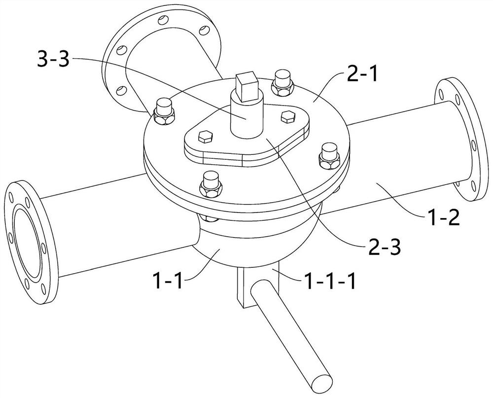
[0060] Refer below figure 1 To illustrate:

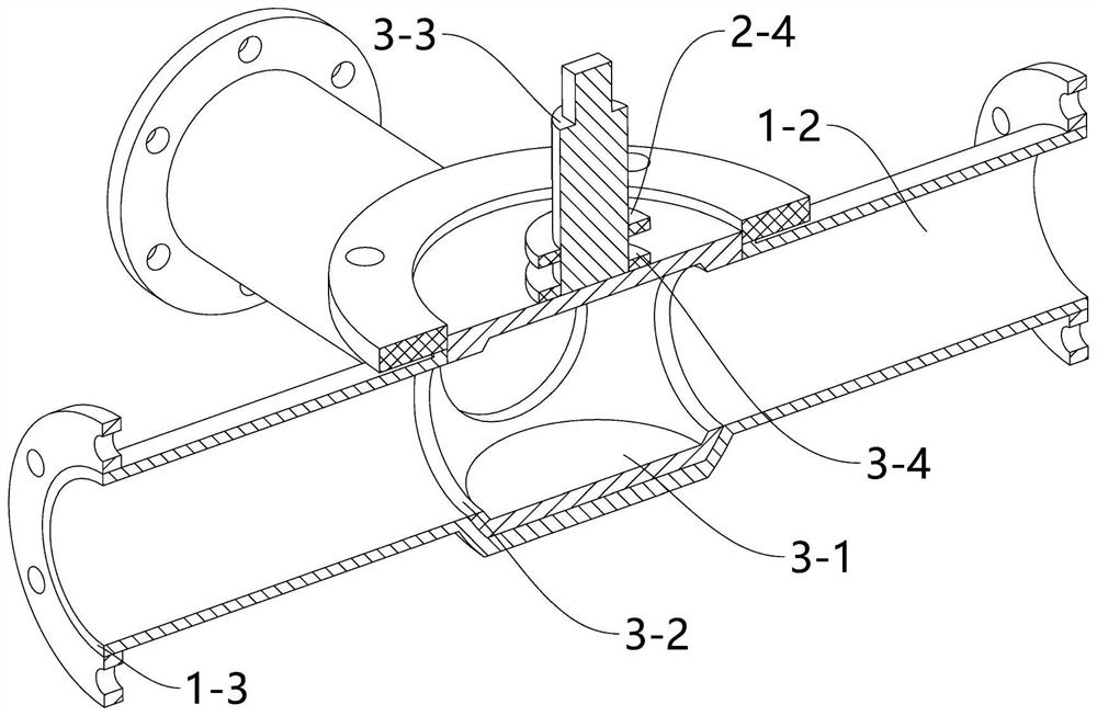
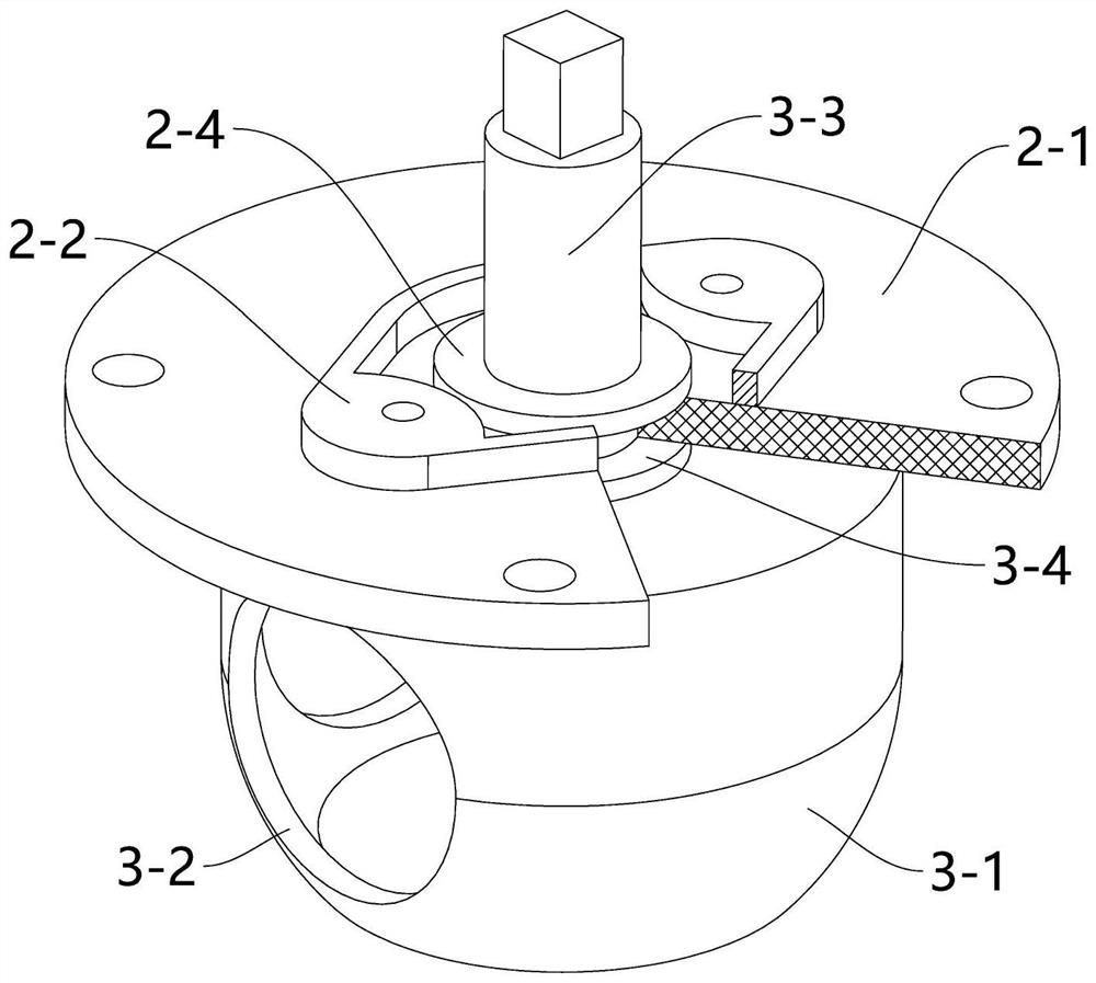
[0061] When the operator holds the valve stem 3-3 tightly, the valve stem 3-3 is manipulated to rotate around the axis of the ball valve spool 3-1. At this time, the ball valve spool 3-1 exerts an Lateral force, so that the housing 1-1 has a tendency to rotate together with the valve stem 3-3. In this way, it will cause twisting damage to the pipeline connected with the three-way ball valve. The hidden danger of leakage of the flange at the connecting pipe of the ball valve;

[0062] Thus, a balance arm 1-1-1 is provided, and the balance arm 1-1-1 and the valve stem 3-3 are respectively arranged at the two ends of the three-way ball valve. When turning the valve stem 3-3, the other hand holds The balance arm 1-1-1, thereby reducing the impact on the housin...


PUM


Abstract

The invention discloses a three-way sealing ball valve. The three-way sealing ball valve comprises a shell, a cover body and a ball valve element; the shell and the cover body are connected through a flange; a cavity is formed by the shell and the cover body; the ball valve element is installed in the cavity; a valve rod is installed on the ball valve element; a balance arm is installed on the shell; a plurality of communicating pipes are arranged on the shell; the axes of the communicating pipes are located on the same plane; and the axes of the communicating pipes are perpendicular to each other. The three-way sealing ball valve has the beneficial effects that when the valve rod is rotated, the balance arm is held by the other hand, so that the influence on the shell when the ball valve element is rotated is reduced, and twisting damage to a pipeline communicated with the three-way ball valve is avoided.

Description

technical field [0001] The invention relates to the technical field of valves, and discloses a three-way sealed ball valve. Background technique [0002] Ball valve (ball valve, the ball of the opening and closing part is driven by the valve stem and rotates around the axis of the ball valve. It can also be used for fluid adjustment and control. Among them, the hard-sealed V-shaped ball valve has a V-shaped ball core and surfacing hard alloy. There is a strong shear force between the metal valve seats, especially suitable for media containing fibers, tiny solid particles, etc. [0003] The existing application number 202020887399.0 is a double-connected three-way ball valve. The utility model relates to a double-connected three-way ball valve, which includes two parallel symmetrically arranged three-way ball valves and a synchronization device arranged between the two three-way ball valves. The synchronization device is detachably connected to the three-way ball valve, the ...

Claims


Application Information

Patent Timeline
Patent Type & Authority Applications(China)
IPC IPC(8): F16K11/087F16K11/085F16K27/06
CPCF16K11/085F16K11/0873F16K27/06
Inventor 韩正海韩雪萍韩文豪王寅陈其保吴跃于刚顾伟明刘祥霞陆程
Owner JIANGSU SUYAN VALVE MASCH CO LTD
Learn More