
A light source device and projection system

A light source device and projection system technology, applied in the direction of projection devices, optics, optical components, etc., can solve the problems of complex design and assembly adjustment, not compact structure, etc., and achieve the effect of simple and easy design, assembly and adjustment, and simple and compact structure

Active Publication Date: 2022-04-26
WUXI SEEMILE LASER DISPLAY TECH
View PDF0 Cites 0 Cited by
  • Summary
  • Abstract
  • Description
  • Claims
  • Application Information

AI Technical Summary

Problems solved by technology

[0004] For some light source devices, dichroic mirrors and reflectors are usually used to meet the combination of excitation light and received light, resulting in an uncompact structure and complicated design, assembly and adjustment.

Method used


Image

  • A light source device and projection system
  • A light source device and projection system
  • A light source device and projection system

Examples


Embodiment Construction

[0042] In the following description, numerous specific details are given in order to provide a more thorough understanding of the present application. It will be apparent, however, to one skilled in the art that the present application may be practiced without one or more of these details. In other examples, some technical features known in the art are not described in order to avoid confusion with the present application.

[0043] It should be understood that the present application can be embodied in different forms and should not be construed as limited to the embodiments set forth herein. Rather, these embodiments are provided so that this disclosure will be thorough and complete, and will fully convey the scope of the application to those skilled in the art. In the drawings, the size and relative sizes of layers and regions may be exaggerated for clarity. Like reference numerals refer to like elements throughout.

[0044] It will be understood that, although the terms ...


PUM


Abstract

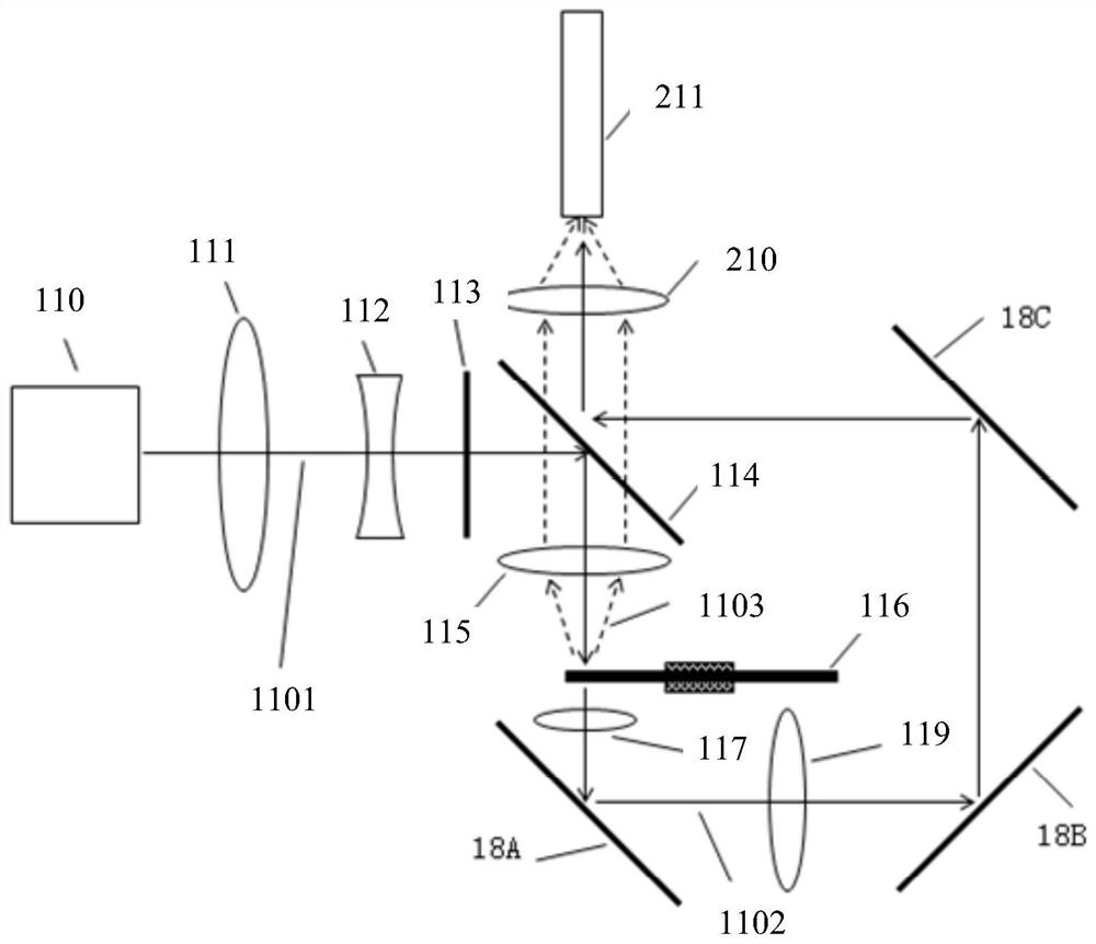
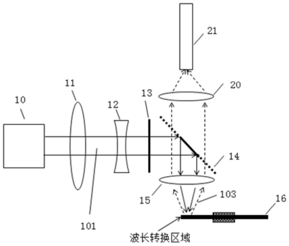
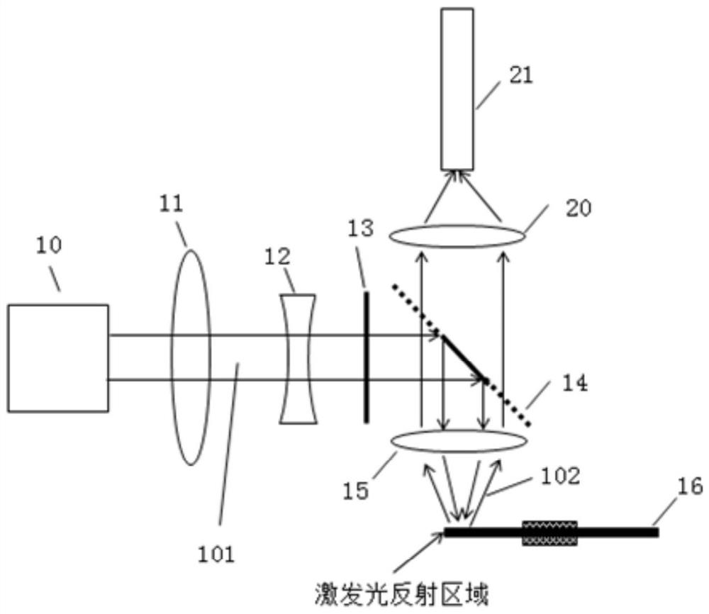
The application discloses a light source device and a projection system. The light source device includes a light source for emitting excitation light; the first area of ​​the light splitting element is for receiving the excitation light emitted by the light source and transmitting or reflecting the excitation light; the wavelength conversion area of ​​the wavelength conversion device It is used to receive the excitation light transmitted or reflected by the first area of ​​the light splitting element to generate the received light; the excitation light reflection area of ​​the wavelength conversion device is used to reflect the excitation light incident on the excitation light reflection area of ​​the wavelength conversion device; when the light is split When the first area of ​​the element is used to transmit the excitation light emitted by the light source, the second area of ​​the light splitting element is used to reflect the excitation light reflected by the wavelength conversion device, and the first area and the second area are used to reflect the stimulated light; or, when When the first area of ​​the light splitting element is used to reflect the excitation light emitted by the light source, the second area of ​​the light splitting element is used to transmit the excitation light reflected by the wavelength conversion device, and the first area and the second area are used to transmit the received light.

Description

technical field [0001] The present application relates to the field of display technology, in particular to a light source device and a projection system. Background technique [0002] Laser is a light source with high brightness, strong directionality, and monochromatic coherent light beam. Due to its many advantages, it has been gradually used as a light source in the field of projection display technology in recent years. In the field of display, as far as the realization of white light is concerned, using high-power blue LEDs or blue LDs to excite fluorescent substances and make them excited to obtain a combination of green, yellow, and red light to synthesize white light is a current white light solution. , this scheme has gradually attracted the attention of researchers in the industry because of its simplicity and low cost. [0003] In the current laser projection display products, most of the laser light source systems use laser-excited phosphors to emit light to re...

Claims


Application Information

Patent Timeline
Patent Type & Authority Patents(China)
IPC IPC(8): G03B21/20G02B27/14
CPCG03B21/204G03B21/2066G03B21/206G02B27/141G03B21/208
Inventor 葛明星陈龙
Owner WUXI SEEMILE LASER DISPLAY TECH
Learn More