Plugging end positioning device for mobile USB flash disk

A technology of positioning device and plug-in terminal, which is applied in the computer field, can solve the problems of stress damage to the plug-in terminal of the U disk, reduced work efficiency, and low practical performance of equipment, so as to avoid the reduction of work efficiency and improve the practical performance.

Inactive Publication Date: 2021-08-10
杭州苏资电子商务有限公司
View PDF3 Cites 0 Cited by
  • Summary
  • Abstract
  • Description
  • Claims
  • Application Information

AI Technical Summary

Problems solved by technology

[0002] At present, during the use of the corresponding smart-manufactured computer U disk plug-in device, if there is dust in the slot or dust is accidentally attached to the plug-in end of the U-disk, it will cause the U-disk to be inserted into the plug-in terminal in the later stage. After being inserted into the slot, poor contact occurs and the corresponding work efficiency is reduced. In addition, because only a small part of the U disk is connected to the slot, when the external shaking force acts on the computer, the part of the U disk that extends outward The impact of gravity will cause the U disk to loosen as a whole, and when the U disk is not subjected to a force parallel to the insertion direction when the U disk is unplugged, it will also cause stress damage to the plug-in end of the U disk
[0003] Aiming at the deficiencies of the prior art, the present invention provides a plug-in terminal positioning device for a mobile U disk, which has the advantages of avoiding the reduction of work efficiency due to poor contact and effectively improving the practical performance of the equipment, and solves the problem of general During the use of the plug-in terminal device for the mobile U disk, the corresponding work efficiency will be reduced due to poor contact, and the practical performance of the equipment will be low.

Method used


Image

  • Plugging end positioning device for mobile USB flash disk
  • Plugging end positioning device for mobile USB flash disk
  • Plugging end positioning device for mobile USB flash disk

Examples


Embodiment 1

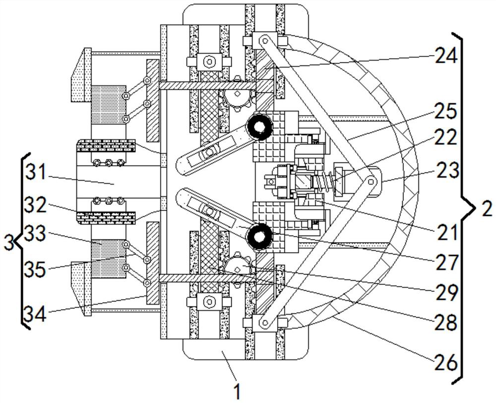
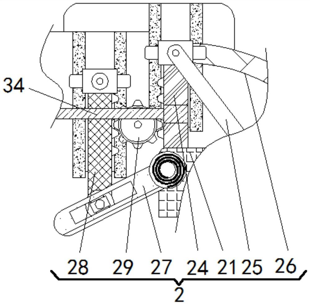
[0022] see figure 1 , 2 And 4, a plug-in terminal positioning device for moving U disk, including a housing 1, the right part of the inner cavity of the housing 1 is fixedly connected with an air blowing mechanism 2, and the left part of the inner cavity of the housing 1 is movably connected with a positioning mechanism 3. The air blowing mechanism 2 includes an electromagnetic seat 21, an elastic ventilation rod 22, a magnetic block 23, a rack 24, a pole 25, an air bag ring 26, a sealing plate 27, a gear rod 28, and a transmission gear 29. After the electromagnetic seat 21 is energized The magnetic poles on the adjacent surface of the magnetic block 23 are opposite, and the two attract each other. The middle part of the electromagnetic seat 21 is slidingly inserted with an elastic air passage rod 22, and the right end of the elastic air passage rod 22 is fixedly connected with a magnetic block 23. The upper and lower sides of the electromagnetic seat 21 Both ends are slidabl...

Embodiment 2

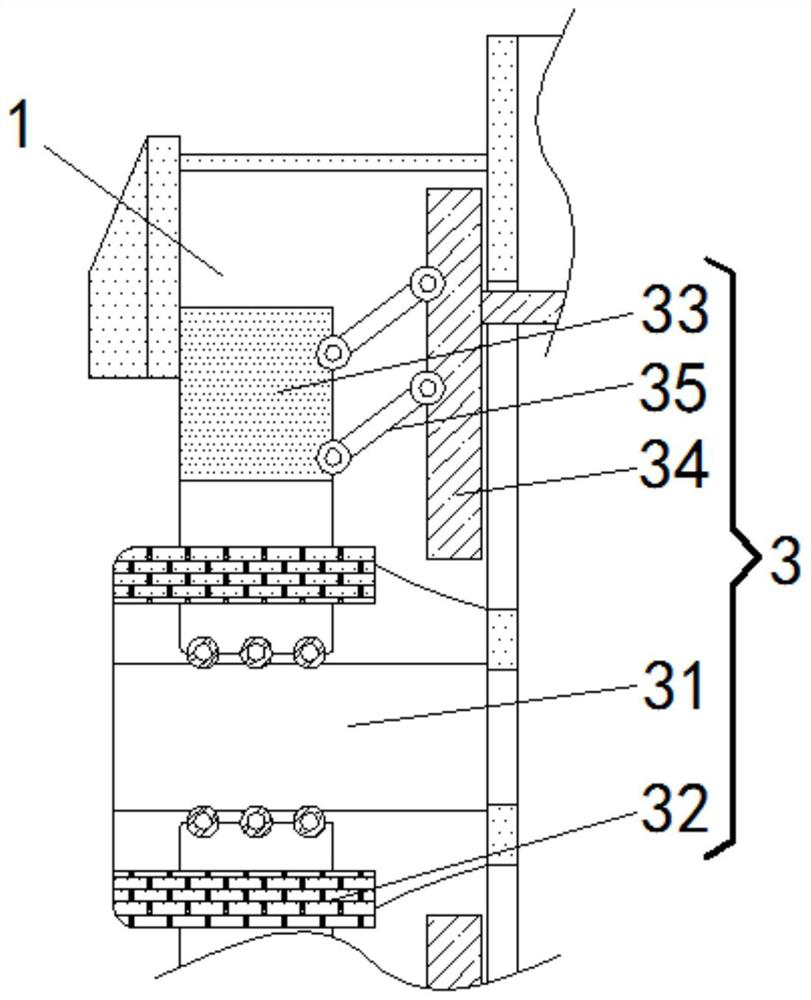
[0024] see figure 1 with 3 A plug-in terminal positioning device for moving a U disk, comprising a housing 1, the right part of the inner cavity of the housing 1 is fixedly connected with an air blowing mechanism 2, and the left part of the inner cavity of the housing 1 is movably connected with a positioning mechanism 3, The positioning mechanism 3 includes a plug-in slot 31, a photoresistor frame 32, an abutment block 33, a linkage plate 34, and a connecting rod 35. The inner cavity of the plug-in slot 31 is fixedly connected with a photoresistor frame 32, and the upper and lower sides of the plug-in slot 31 The abutment block 33 is slidably connected, and the abutment block 33 is provided with an abutment groove near the side of the photoresistor frame 32, so that after the abutment groove on the abutment block 33 is snapped to the side wall of the photoresistor frame 32, It can move laterally to the outside of the housing 1 under the push of the connecting rod 35, and sta...

Embodiment 3

[0026] see Figure 1-4, a plug-in terminal positioning device for moving a U disk, comprising a housing 1, the right part of the inner cavity of the housing 1 is fixedly connected with an air blowing mechanism 2, and the air blowing mechanism 2 includes an electromagnetic seat 21, an elastic air passage rod 22, Magnetic block 23, tooth bar 24, pole 25, airbag ring 26, sealing plate 27, tooth bar 28, transmission gear 29, after electromagnetic seat 21 energizes, the magnetic pole of adjacent surface with magnetic block 23 is opposite, and the two attract each other, electromagnetic The middle part of the seat 21 is slidably connected with an elastic air passage rod 22, and the right end of the elastic air passage rod 22 is fixedly connected with a magnetic block 23, and the upper and lower ends of the electromagnetic seat 21 are slidably connected with a rack 24, the rack 24 and the magnetic block 23. A support rod 25 is movably connected between them, an air bag ring 26 is fix...


PUM


Abstract

The invention relates to the technical field of computers, and discloses a plugging end positioning device for a mobile USB flash disk. The plugging end positioning device comprises a shell, wherein the right part of the inner cavity of the shell is fixedly connected with an air blowing mechanism, and the left part of the inner cavity of the shell is movably connected with a positioning mechanism. According to the plugging end positioning device for moving the USB flash disk, the USB flash disk is plugged into a plug-in groove, so the light receiving quantity of a photoresistor frame is changed, the capacity of an electromagnetic seat for attracting a magnetic block is reduced, a sealing plate is opened, a sealing space formed by a supporting rod and an air bag ring shrinks, and then an elastic air ventilation rod can blow air to the plug-in groove and the USB flash disk so as to remove dust and guarantee stable contact; and racks on two sides drive linkage plates to move in opposite directions, so abutting blocks move towards the outside of the shell while fastening the USB flash disk, and then limiting stability is improved, so the situation that working efficiency is reduced due to poor contact is avoided, and the practical performance of equipment use is effectively improved.

Description

technical field [0001] The invention relates to the technical field of computers, in particular to a plug-in end positioning device for a mobile U disk. Background technique [0002] At present, during the use of the corresponding smart-manufactured computer U disk plug-in device, if there is dust in the slot or dust is accidentally attached to the plug-in end of the U-disk, it will cause the U-disk to be inserted into the plug-in terminal in the later stage. After being inserted into the slot, poor contact occurs and the corresponding work efficiency is reduced. In addition, because only a small part of the U disk is connected to the slot, when the external shaking force acts on the computer, the part of the U disk that extends outward The impact of gravity will cause the U disk to loosen as a whole, and when the U disk is not subjected to a force parallel to the insertion direction when the U disk is unplugged, it will also cause stress damage to the plugged end of the U d...

Claims


Application Information

Patent Timeline
Patent Type & Authority Applications(China)
IPC IPC(8): H01R13/639H01R43/00B08B5/02
CPCH01R13/639H01R43/002B08B5/02H01R2201/06
Inventor 詹恬
Owner 杭州苏资电子商务有限公司
Why Eureka
Try Eureka