Dielectric Barrier Discharge Lamps

A dielectric barrier, discharge lamp technology, applied in the direction of discharge lamps, gas discharge lamps, gas discharge lamp parts, etc., can solve problems such as breakage, cracks, and discharge vessel damage

Active Publication Date: 2017-04-12
GS YUASA INT LTD
View PDF6 Cites 0 Cited by
  • Summary
  • Abstract
  • Description
  • Claims
  • Application Information

AI Technical Summary

Problems solved by technology

[0012] However, in the above-mentioned conventional dielectric barrier discharge lamp, if the entire left and right side wall plates of the discharge vessel are made of a light-shielding member, or if a light-shielding film that blocks ultraviolet rays is formed on the entire inner surface, there is a problem that the amount of ultraviolet irradiation light is reduced. The problem
[0013] In addition, in the above-mentioned conventional dielectric barrier discharge lamp, since the discharge vessel is mainly composed of quartz, if the discharge vessel is continuously irradiated with extremely high ultraviolet energy, cracks may occur in the area where the light-shielding film is formed, causing the When the discharge vessel is damaged
When the cross-section of the left and right side wall plates of the discharge vessel is bent so as to protrude outward, if there is no light-shielding film, damage may occur near the top of the bend.
In addition, even when the light-shielding film is formed near the top of the curve on the inside surfaces of the left and right side wall panels, there are cases where the discharge vessel is broken near the short edge portion of the light-shielding film in the accelerated test.

Method used


Image

  • Dielectric Barrier Discharge Lamps
  • Dielectric Barrier Discharge Lamps
  • Dielectric Barrier Discharge Lamps

Examples


no. 1 approach

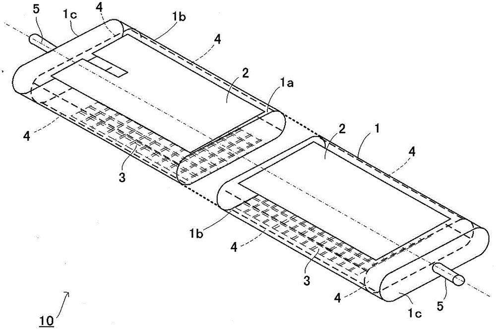
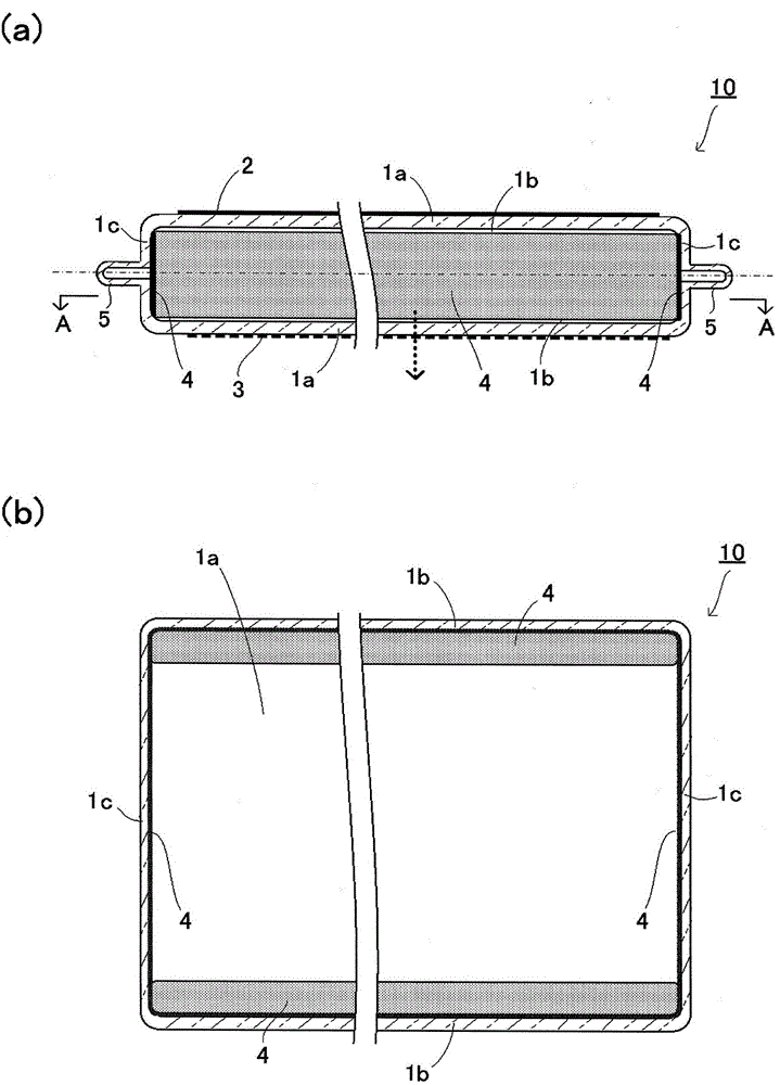
[0096] figure 2 and image 3 It is a figure which shows an example of the 1st Embodiment of this invention, figure 2 It is a perspective view omitting the vertically long central part of the dielectric barrier discharge lamp, image 3 yes figure 2 cutaway view. image 3 (a) is to figure 2 The sectional view obtained by cutting the discharge vessel at the longitudinal central axis and viewing it from the side direction, image 3 (b) is along image 3 A-A line cross-sectional view seen in the arrow direction of (a). In addition, the one-dot chain line in a figure shows the vertically long central axis.

[0097] It should be noted, figure 2 and image 3 The structure is the same as that of the first aspect, so the description is omitted.

[0098] Figure 10 It is a figure which shows an example of 1st Embodiment of this invention, and is a cross-sectional view perpendicular to the longitudinal direction of a dielectric barrier discharge lamp. Figure 10 The singl...


PUM


Abstract

The invention provides a dielectric barrier discharge lamp used for vacuum ultraviolet irradiation, wherein the amount of the ultraviolet light irradiation is reduced, and a discharge vessel is protected from damage. Left and right side plates are arranged in the cross sections parallel with the front and back side plates and are bended to be convex towards to the exterior of the discharge vessel, shading films are formed on the inner side surface of the left and right side plates, the top and inner sides of the bended left and right side plates are covered by shading films, the shading films are positioned in the cross section parallel with the front and back side plates, the line connecting an intersection point with one end of the shading film forms an angle from 60 to 180 DEGs with the line connecting the intersection point with the other end of the shading film, wherein the intersection point is formed by the intersection of the middle line of upper and lower plates and the left and right side plates, or the intersection point with one end of the shading film forms an angle less than 180 DEGs with the line connectiong the intersection point with the other end of the shading film, and the ultraviolet transmissibility of the shading film is from 16% to 86%.

Description

technical field [0001] The present invention relates to a dielectric barrier discharge lamp for irradiating vacuum ultraviolet rays. Background technique [0002] In recent years, dielectric barrier discharge lamps are known in which the shape of the discharge tube has a flat surface on the irradiation side (Patent Documents 1, 2, 3, etc.). This dielectric barrier discharge lamp has the advantage that an ultraviolet irradiation device can be manufactured at low cost by being connected to a predetermined power supply device, and can directly irradiate a subject to be irradiated with vacuum ultraviolet rays. [0003] Patent Document 1 describes a technique in which, in a dielectric barrier discharge lamp formed in an extremely elongated shape front and rear, by forming "Vacuum UV protective layer" to suppress the deterioration of the front and rear end panels or the left and right side panels (paragraphs 10 and 11, etc.). In addition, Patent Document 2 describes a technique ...

Claims


Application Information

Patent Timeline
Patent Type & Authority Patents(China)
IPC IPC(8): H01J61/30H01J61/35
CPCH01J61/025H01J61/302H01J65/046
Inventor 片桐毅畑濑和也
Owner GS YUASA INT LTD
Why Eureka
Try Eureka