Digital video recorder error recovery method

A technology of digital video and video recording, applied in the direction of digital signal error detection/correction, digital recording/reproduction, data recording, etc., can solve problems such as conflicts

Inactive Publication Date: 2003-12-24
THOMSON CONSUMER ELECTRONICS INC
View PDF0 Cites 0 Cited by
  • Summary
  • Abstract
  • Description
  • Claims
  • Application Information

AI Technical Summary

Problems solved by technology

May create conflicts between requirements for various devices

Method used


Image

  • Digital video recorder error recovery method
  • Digital video recorder error recovery method
  • Digital video recorder error recovery method

Examples


Embodiment Construction

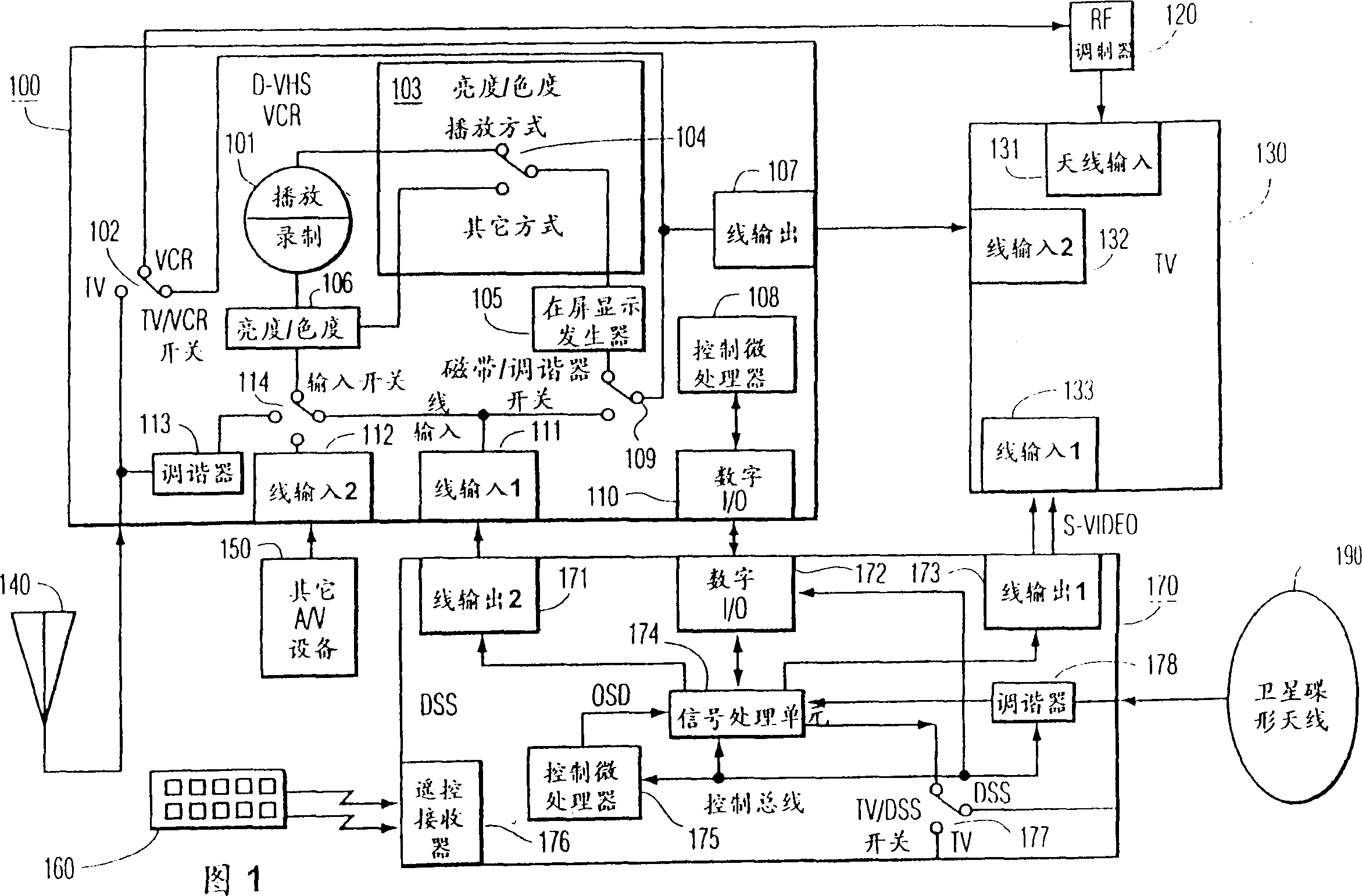
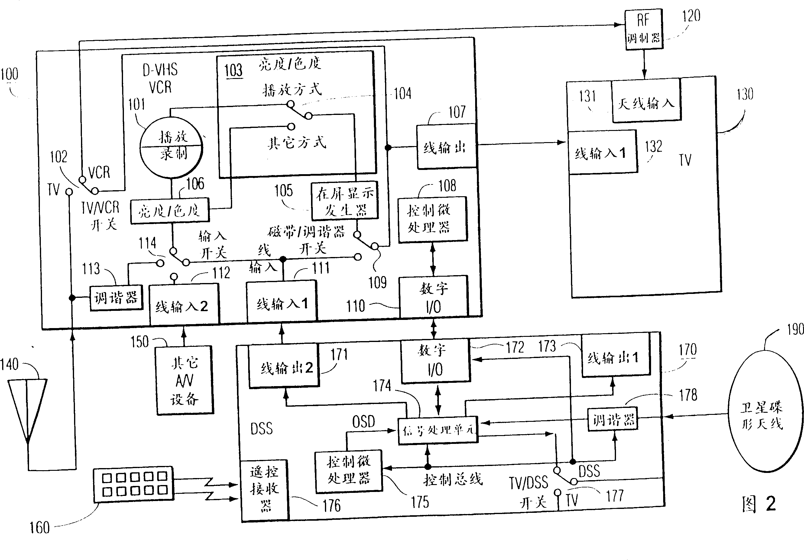
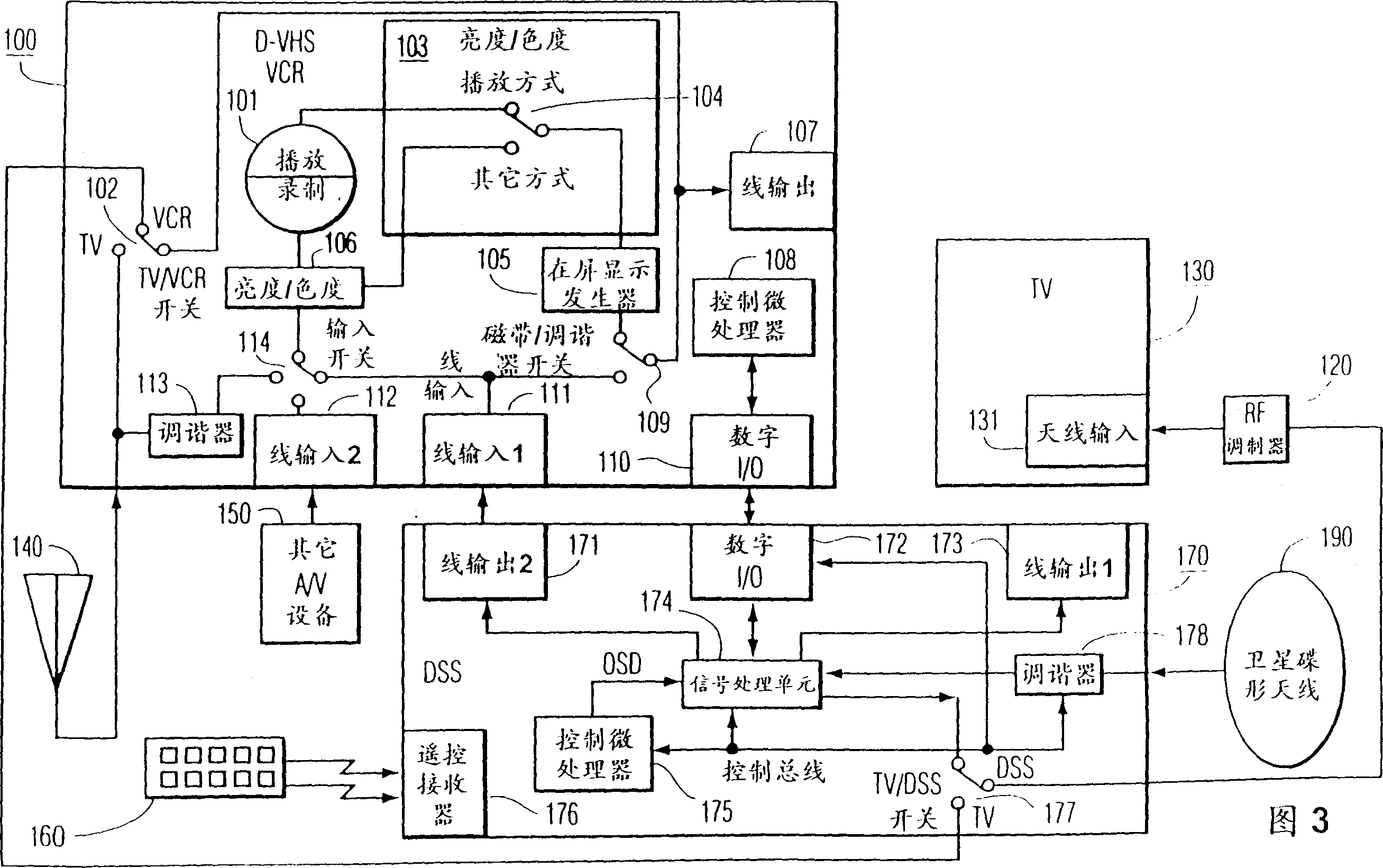
[0019] Figure 1 shows an interface system of multiple electronic devices. These devices include a DVHSVCR100, a DSS unit 170, a TV130, another A / V device 150, an antenna 140 for receiving broadcast signals, and a remote controller 160 as an interface between the user and the DSS unit 170, A satellite dish 190 receiving DSS signals, and an RF modulator 120. The VCR 100 includes a playback / recording circuit 101, which receives the signal to be recorded from the luminance / chrominance processor 106. The circuit 101 outputs a signal to the luminance / chrominance processor 103 during playback. The processor 103 also includes a switch 104 which guides the signal as shown in the figure during the playback mode and during other modes. The VCR 100 also includes a tuner 113 for tuning a desired channel from the signal generated by the antenna 140, and line inputs 111 and 112 for receiving composite television signals from the line output 171 of the other A / V equipment 150 and the DSS unit 170...


PUM


Abstract

A method for operating a video recording apparatus in one of a digital recording mode and an analog recording mode. The method involves recording a digital video bit stream in the digital recording mode and switching to the analog recording mode for recording the corresponding analog video signal in response to a fault condition. For example, the fault conditions may occur in response to improper copyright information , an analog recording media being loaded into the video recording apparatus or the digital video bit stream being absent while the video recording apparatus operates in the digital recording mode. The fault condition may be indicated to a user and switching to a different mode, such as the analog recording mode, may occur in response to receiving a user initiated command responsive to the indicated fault condition.

Description

Technical field [0001] The present invention relates to a system for communication between multiple electronic devices (eg, consumer electronic devices) interconnected by, for example, a digital data bus. Background technique [0002] Protocols such as the consumer electronic device bus or data bus called CEBus can be used to interconnect consumer electronic devices such as televisions, display devices, video recorders (VCR) and direct broadcast satellite (DBS) receivers. Bus protocols such as CEBus can transmit control information as well as data. CEBus control information is communicated on a "control channel" that has a protocol defined in the Electronic Equipment Industry Association (EIA) Performance Specification IS-60. A programming language called "CAL" (Common Application Language) can be used to define control information for special applications. [0003] Consumer electronic devices are becoming more and more complex, and their functions are increasing. It may be neces...

Claims


Application Information

Patent Timeline
Patent Type & Authority Patents(China)
IPC IPC(8): G11B15/02G11B20/00G11B20/10G11B20/18H04L9/32H04L12/22H04L12/28H04L12/40H04L12/403H04L12/64H04L29/06H04L29/08H04N5/44H04N5/445H04N5/76H04N5/765H04N5/775H04N5/782H04N5/91H04N5/913H04N5/92H04N5/926H04N5/93H04N7/08H04N7/081H04N9/79
CPCG11B20/00086H04N9/7925G11B20/0021H04N21/4147G11B20/10H04N2005/91321G11B20/00137H04L2012/4026H04L29/06H04L2012/2841H04N21/4104H04N21/488H04N21/47214H04N7/163G11B20/00543H04L12/403H04L12/2803H04N5/775H04L67/325G11B20/0084H04N5/7755H04L67/12H04L12/40117H04N5/9305H04N5/765H04L12/413H04L12/2814G11B20/00666H04N5/782G11B20/00152H04L67/42H04L12/2805H04L12/2809H04N9/7921H04N21/4627H04N21/8355H04L12/282G11B20/00753H04N21/43615H04N21/4882H04N2005/91328G11B20/00144H04N21/4583H04N5/4401H04L69/329H04N21/4334H04N5/913G11B20/0071H04L2012/2849H04N21/4227H04N21/4753H04N5/926H04L67/327H04N21/426H04N21/4112H04L67/63H04L67/62H04L12/28H04L65/00H04L9/40H04L67/01
Inventor K·F·霍尔兰德小M·F·克温图斯R·H·米勒K·R·维梅耶尔
Owner THOMSON CONSUMER ELECTRONICS INC
Why Eureka
Try Eureka