
Camera control method and system, server and control equipment

A technology for control equipment and control methods, applied in the field of camera control methods, servers and control equipment, and systems, can solve the problems of omission and the entrance is still on the control equipment, and achieve the effect of reducing the risk of omission, avoiding configuration changes, and improving efficiency

Active Publication Date: 2021-08-10
BANK OF CHINA
View PDF13 Cites 0 Cited by
  • Summary
  • Abstract
  • Description
  • Claims
  • Application Information

AI Technical Summary

Problems solved by technology

[0003] At present, the existing technology controls the cameras in the current network through the control equipment deployed at each network point, and assigns a dedicated camera ID to the camera for server identification. However, because the server only manages the camera ID, the camera is configured specifically. The entrance of the camera is still on the control device. When it is necessary to modify the configuration information, it still needs to be configured through the smart device of the outlet. There is a problem that multi-point configuration is required. If the camera identification set by the server needs to be modified uniformly, it may be necessary to The smart devices of all outlets are modified once, then the risk of omission will be greatly increased

Method used


Image

  • Camera control method and system, server and control equipment
  • Camera control method and system, server and control equipment
  • Camera control method and system, server and control equipment

Examples


Embodiment Construction

[0050] The following will clearly and completely describe the technical solutions in the embodiments of the application with reference to the drawings in the embodiments of the application. Apparently, the described embodiments are only some of the embodiments of the application, not all of them. Based on the embodiments in this application, all other embodiments obtained by persons of ordinary skill in the art without making creative efforts belong to the scope of protection of this application.

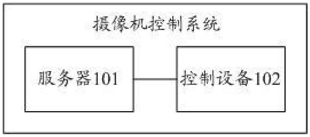
[0051] Such as Figure 1a As shown, it is a schematic diagram of the architecture of a camera control system provided in the embodiment of the present application, including:

[0052] Server 101 and control device 102.

[0053] It should be noted that the specific number of control devices 102 can be set by technicians according to actual conditions.

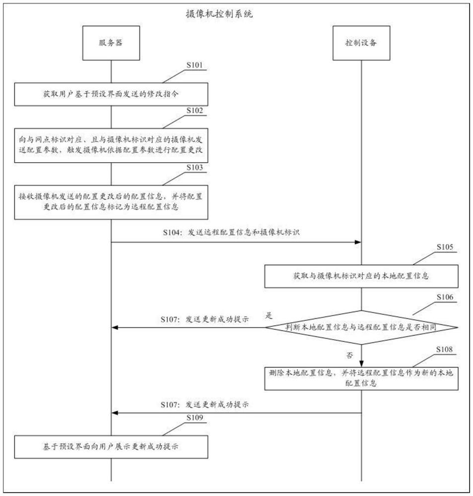
[0054] Among them, using the camera control system to realize the specific process of camera control, such as Figure 1b shown, in...


PUM


Abstract

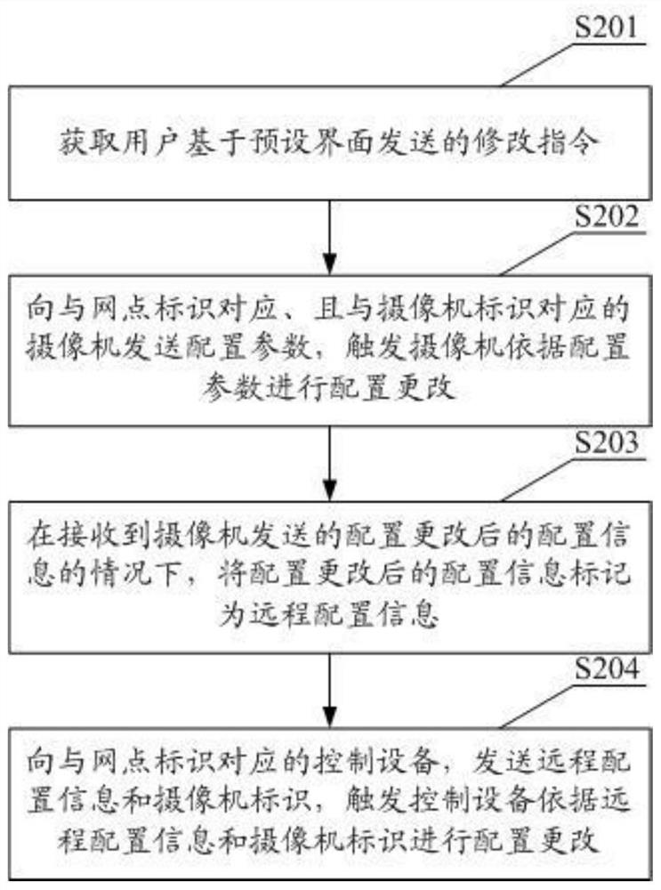
The invention discloses a camera control method and system, a server and control equipment. The method comprises the steps of: obtaining a modification instruction sent by a user based on a preset interface; sending a configuration parameter to a camera corresponding to the network point identifier and the camera identifier, and triggering the camera to carry out configuration change according to the configuration parameter; marking the configuration information as remote configuration information under the condition that the configuration information after configuration change sent by the camera is received; and sending the remote configuration information and the camera identifier to control equipment corresponding to the website identifier, and triggering the control equipment to carry out configuration change according to the remote configuration information and the camera identifier. By using the method of the invention, configuration changes of cameras of all websites can be carried out in the server, and after the configuration changes take effect, the configuration changes are automatically issued to the corresponding control devices for use, thereby achieving the purposes of unified management and simultaneous effect taking, avoiding omission of configuration changes of individual cameras, and reducing the omission risk existing when the configuration of the camera is changed.

Description

technical field [0001] The present application relates to the monitoring field, in particular to a camera control method, system, server and control equipment. Background technique [0002] The open areas of banks (such as self-service cash machines) have the characteristics of 24-hour operation and are widely distributed. If special personnel are arranged to guard them, it will be a serious burden on human resources. Therefore, most of them adopt the deployment of surveillance cameras and the installation of The monitoring system performs remote monitoring. However, monitoring tens of thousands of monitoring screens at the same time is also a major burden for users. Therefore, control equipment is deployed in the network, and the early warning information recorded by the camera is sent to the remote monitoring center. The remote monitoring center switches according to the early warning information. The monitoring screen is convenient for users to view the event location. ...

Claims


Application Information

Patent Timeline
Patent Type & Authority Applications(China)
IPC IPC(8): H04N5/232
CPCH04N23/661
Inventor 林熙南吴平凡
Owner BANK OF CHINA
Learn More