Assembling equipment with uniform curing function

A technology for assembling equipment and functions, which can be applied to devices for coating liquids on surfaces, pretreatment surfaces, coatings, etc., which can solve the problems of reducing the quality of camera assembly and the difficulty of uniform curing of adhesives, so as to improve the quality of assembly and improve the The effect of uniformity

Active Publication Date: 2021-08-13
TZTEK TECH
7 Cites 0 Cited by

AI-Extracted Technical Summary

Problems solved by technology

[0003] Generally, a number of UV lamps are distributed around the fixture to irradiate and cure the glue on the parts to be assembled. However, other devices are i...

Method used

For ease of understanding, the main camera 21 and the secondary camera 22 of the embodiment of the present invention are illustrated by Fig. 1, the first material to be assembled is the secondary camera 22 in the camera of a mobile phone, and the second material to be assembled is the camera of a mobile phone The main camera 21, the main camera 21 has been fixedly installed on the bracket 23, and the bracket 23 also includes a mounting slot for installing the sub-camera 22, as shown in Figure 1, the mounting bracket in Figure 1 is provided with two mounting slots , one is used to install the main camera 21, and the other is used to install the sub-camera 22. In the embodiment of the present invention, the main camera 21 has been fixedly installed on the bracket 23 as a second material to be assembled for loading as a whole, and the sub-camera 22 Loading is carried out as the first material to be assembled. The assembly equipment provided by the embodiment of the present invention directly irradiates the glue on the bracket through the UV light to make the glue between the sub-camera and the bracket evenly cured after the adjustment component adjusts the posture of the sub-camera to match the main camera.
Specifically, as shown in Figures 2 to 9, the embodiment of the present invention provides an assembly device with a uniform curing function, including an alignment assembly 5 and a curing assembly 6, wherein the alignment assembly 5 includes a carrier 51 , the suction assembly and the adjustment assembly 52, the stage 51 is fixedly connected with the adjustment assembly 52, the suction assembly is fixedly installed on the stage 51, the adjustment assembly 52 is ...

Abstract

The invention provides assembling equipment with a uniform curing function. The equipment comprises an alignment assembly and a curing assembly, wherein the alignment assembly comprises a carrying table, a suction assembly and an adjusting assembly, the adjusting assembly is used for adjusting the posture of a first to-be-assembled material piece, and the suction assembly is used for sucking or loosening the first to-be-assembled material piece. The curing assembly comprises a UV lamp, and light emitted by the UV lamp is used for curing an adhesive on a support so that the first to-be-assembled material piece can be fixed to the support. According to the alignment device, the posture of the first to-be-assembled material piece is adjusted through the adjusting assembly so as to be matched with a second to-be-assembled material piece fixed to the support, and after alignment of the first to-be-assembled material piece and the second to-be-assembled material piece is completed, the adhesive on the support is cured through the UV lamp installed on the carrying table so that the first to-be-assembled material piece can be fixed to the support; and light emitted by the UV lamp penetrates through the carrying table and a jig to irradiate the adhesive, so that the curing uniformity of the adhesive is improved, and the assembly quality of camera assembly is further improved.

Application Domain

Technology Topic

Image

  • Assembling equipment with uniform curing function
  • Assembling equipment with uniform curing function
  • Assembling equipment with uniform curing function

Examples

  • Experimental program(1)

Example Embodiment

[0033] In order to make the purpose, technical solutions and advantages of the embodiments of the present invention clearer, the technical solutions of the embodiments of the present invention will be clearly and completely described below with reference to the accompanying drawings of the embodiments of the present invention. Obviously, the described embodiments are some, but not all, embodiments of the present invention. Based on the described embodiments of the present invention, all other embodiments obtained by those of ordinary skill in the art fall within the protection scope of the present invention.
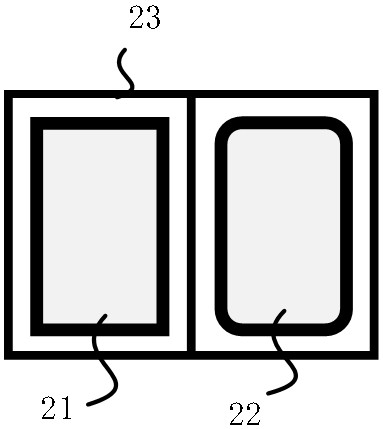
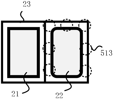
[0034] The present invention relates to the assembly of a camera. The camera may be a camera on electronic products such as a computer camera, a mobile phone camera, a camera camera, etc. The embodiment of the present invention uses a mobile phone camera to describe the following embodiments.
[0035] An embodiment of the present invention provides an assembling device with a uniform curing function. The assembling device installs a curing component on a carrier, so that the adjustment component adjusts the posture of the first to-be-assembled material to match the second to-be-assembled material After that, the UV lamp irradiates the adhesive on the bracket and the first component to be assembled, so that the adhesive is cured and the first component to be assembled is fixed on the bracket to complete the second component to be assembled and the first component to be assembled. Assembly of the parts to be assembled.
[0036] For ease of understanding through figure 1 The main camera 21 and the sub camera 22 in the embodiment of the present invention will be described. The first component to be assembled is the sub camera 22 in the camera of the mobile phone, and the second component to be assembled is the main camera 21 in the camera of the mobile phone, and the main camera 21 has been fixed. It is mounted on the bracket 23, and the bracket 23 also includes a mounting slot for mounting on the sub-camera 22, such as figure 1 shown, figure 1 There are two installation slots on the mounting bracket in 23 is used as a whole to be loaded, and the sub-camera 22 is used as the first to be assembled material to be loaded. The assembling device provided by the embodiment of the present invention directly irradiates the glue on the bracket through the UV lamp after the adjustment component adjusts the posture of the sub-camera to match the main camera, so that the glue between the sub-camera and the bracket is uniformly cured.
[0037] Specifically, as Figure 2 to Figure 9 As shown, the embodiment of the present invention provides an assembly device with a uniform curing function, including an alignment component 5 and a curing component 6, wherein the alignment component 5 includes a carrier 51, a suction component and an adjustment component 52, the carrier 51 and the The adjustment component 52 is fixedly connected, the suction component is fixedly installed on the carrier 51, the adjustment component 52 is used to adjust the posture of the first to-be-assembled material, and the suction component is used to suck or loosen the first to-be-assembled material, that is, a secondary camera. The suction assembly fixedly installed on the stage 51 is used to adsorb the sub-photograph on the stage and place it in the sub-photograph installation groove of the bracket. The transmission mechanism used for the suction assembly is not specifically described in the embodiment of this application. The core of the embodiment is that the curing component 6 is installed on the stage 51 to directly irradiate and cure the sub-camera 22 and the bracket 23, so that the glue is uniformly cured.
[0038]The curing component 6 includes a UV lamp, and the light emitted by the UV lamp is used to cure the adhesive on the bracket 23, so that the first to-be-assembled material is fixed on the bracket 23; wherein, the first to-be-assembled material is adjusted after the adjustment component. The second to-be-assembled material fixedly installed on the matching bracket is matched. The dispensing mechanism applies glue to the installation groove on the bracket, and the secondary camera adjusts its posture in the installation groove by adjusting the component to match the second to-be-assembled material. When the secondary-photograph's posture matches the second to-be-assembled material, the main camera After that, the UV lamp starts to irradiate the sub-camera and the bracket to cure the glue. The adjustment component 52 also needs to cooperate with equipment such as optical image, 3D profiler, collimator and other equipment in the process of adjusting the sub-photographing posture, namely AA technology.
[0039] The curing component 6 further includes a lampshade, the UV lamp is installed in the lampshade, and the lampshade collects the light emitted by the UV lamp to improve the curing effect.
[0040] In one embodiment, a plurality of through holes 511 are provided on the stage 51 , and the light emitted by the UV lamp passes through the through holes 511 to irradiate the first component to be assembled and the bracket 23 . like figure 2 , Figure 4 and Figure 5 shown, figure 2 The dotted holes in the table are the corresponding positions of the several through holes 511 on the stage on the sub-camera and the bracket. It should be understood that the dotted-line holes are the light emitted by the UV lamp passing through the through holes 511 and directly irradiating the sub-camera 22 and the bracket 23. A light spot 513 is formed in the gap between them to cure the glue. It should be noted figure 2 The dashed hole in is a schematic diagram, and the light is scattered in practice. It should also be noted that: the number of the through holes 511 on the carrier 51 can be set according to specific conditions, so as to achieve the optimal curing effect as a criterion.
[0041] In one embodiment, as Figure 8 and Figure 9 As shown, the suction assembly includes a suction hole 514 , the suction hole 514 is disposed on the carrier 51 , and the suction hole 514 communicates with an air path for sucking the first material to be assembled on the carrier 51 . The stage 51 is provided with an air passage and communicates with the drive assembly, and the suction hole 514 attracts the sub-camera 22 to the stage 51 under the driving force of the drive assembly. Preferably, the suction hole 514 is a semi-through hole, and an air passage communicating with the semi-through hole is provided inside the carrier 51 .
[0042] Further, the suction hole 514 is located between the plurality of through holes 511. Generally, one suction hole 514 on the stage 51 can satisfy the ability of sucking the secondary camera 22. Of course, multiple suction holes can also be set according to specific requirements. For the holes 514, one suction hole 514 is adsorbed at the center position of the sub-camera 22, and the plurality of suction holes 514 are evenly distributed.
[0043] In one embodiment, when the first material to be assembled is adsorbed on the stage 51 under the action of the suction component, the diameter of the through hole 511 is larger than the gap between the first material to be assembled and the bracket 23, and the first Both the assembly material and the bracket 23 overlap with the through hole 511 . In this embodiment, the light emitted by the UV lamp passes through the through hole 511 so that more light is irradiated in the gap between the sub-camera 22 and the bracket 23, so as to directly cure the glue and improve the curing effect of the glue.
[0044] In one embodiment, as Image 6 and Figure 7 As shown, the stage 51 is provided with a step 512 , and the step 512 is located at the through hole 511 to increase the distance between the first component to be assembled and the through hole 511 . Increasing the distance between the first component to be assembled and the through hole 511 expands the irradiation range of the UV lamp, and further improves the curing effect and curing efficiency. Figure 7 Only a part of the steps 512 are shown in the figure, and the setting of the steps 512 can be set according to the specific situation, taking the increase of the irradiation range as the criterion.
[0045] In one embodiment, a jig 54 is further included. The jig 54 includes a first part and a second part, the first part is fixedly mounted on the carrier 51 , and the second part can move relative to the first part. In the embodiment of the present invention, the AA technology is used to make the posture of the sub-camera match the main camera. Before performing AA, a lighting fixture for the secondary camera is required, and of course, a lighting fixture for the main camera is also required. Specifically, the sub-camera 22 uses the on-off assembly 53 to light the fixture 54. The on-off assembly 53 includes a first drive assembly 531 and a lifter. One end of the lifter is fixedly connected to the second part, and the other end is fixedly connected to the first drive assembly. The second part moves relative to the first part under the driving force of the first driving component 531 to clamp or release the first material to be assembled. The first driving assembly 513 is preferably driven by an air cylinder, of course, it is not limited to being driven by an air cylinder. When the sub-camera 22 needs to light up the fixture 54, the second part follows the lifting member to move up and down under the driving of the cylinder, so that the soft connection 221 of the sub-camera is clamped between the first part and the second part of the fixture, so as to realize Light up the fixture.
[0046] It should be noted that: on the one hand, the lighting fixture is to turn on the power supply, and on the other hand, it can obtain the relevant data of the sub-camera, such as the position data of the sub-camera. The main camera 21 also needs to light up the fixture, and the main camera fixture and the sub camera fixture have the same function.
[0047] like Figure 4 As shown, the adjustment component 52 is preferably a six-axis adjustment member, and the adjustment component 52 can adjust the six axes of X, Y, Z, U, V, and W of the sub-camera, so that its posture matches the main camera.
[0048] Specifically, the adjustment assembly 52 includes a displacement adjustment module, and the displacement adjustment module includes a first direction assembly, a second direction assembly and a third direction assembly, wherein the first direction assembly includes a second drive assembly, a first slider 522 and The first sliding rail 521, the first sliding block 522 is slidably connected to the first sliding rail 521, and the first sliding block 522 reciprocates along the direction of the first sliding rail 521 under the driving force of the second driving component, that is, along the image 3 Movement in the X-axis direction of the coordinate system shown in .
[0049] The second direction assembly includes a third driving assembly, a second sliding block 524 and a second sliding rail 523, the second sliding block 524 is slidably connected with the second sliding rail 523, and the second sliding rail 523 and the third driving assembly are fixedly installed on the first On a sliding block 522, the second sliding block 524 reciprocates along the direction of the second sliding rail 523 under the driving force of the third driving component, that is, along the image 3 Movement in the Y-axis direction in the coordinate system shown.
[0050] The third direction assembly includes a fourth driving assembly, a third sliding block 526 and a third sliding rail 525. The third sliding block 526 is slidably connected to the third sliding rail 525, and the fourth driving assembly and the third sliding rail 525 are fixedly installed on the third sliding rail 525. On the two sliding blocks 524, the third sliding block 526 reciprocates along the direction of the third sliding rail 525 under the driving force of the fourth driving component, that is, along the image 3 Movement in the direction of the Z axis in the coordinate system shown. The second drive assembly, the third drive assembly and the fourth drive assembly are preferably linear motors, but of course not limited to linear motors.
[0051] Further, the adjustment assembly 52 also includes an angle adjustment module, the angle adjustment module is mounted on the third slider, the angle adjustment module includes a first rotation axis, a second rotation axis and a third rotation axis, the first rotation axis, The second rotating shaft and the third rotating shaft respectively include a fifth driving assembly 527, a sixth driving assembly 528 and a seventh driving assembly 529, the third rotating shaft is connected to the carrier, and the first material to be assembled is connected to the fifth driving assembly 527, The angle attitude adjustment is performed under the driving of the sixth driving assembly 528 and the seventh driving assembly 529 . The fifth drive assembly 527 , the sixth drive assembly 528 and the seventh drive assembly 529 are preferably stepping motors, but are not limited to stepping motors.
[0052] The above are the preferred embodiments of the present invention. It should be pointed out that for those skilled in the art, without departing from the principles of the present invention, several improvements and modifications can be made. It should be regarded as the protection scope of the present invention.

PUM

no PUM

Description & Claims & Application Information

We can also present the details of the Description, Claims and Application information to help users get a comprehensive understanding of the technical details of the patent, such as background art, summary of invention, brief description of drawings, description of embodiments, and other original content. On the other hand, users can also determine the specific scope of protection of the technology through the list of claims; as well as understand the changes in the life cycle of the technology with the presentation of the patent timeline. Login to view more.

Similar technology patents

Folded light path LED array collimation optic

ActiveUS20100039822A1Improve uniformityDegradation of intensityLighting applicationsMechanical apparatusPhysicsColor mixing
Owner:LIGHTING SCI GROUP

Classification and recommendation of technical efficacy words

  • Improve uniformity
  • Improve assembly quality

General method for laying out and assembling wedge-shaped duct pieces

InactiveCN103758531ASimplify the manufacturing and assembly processImprove assembly qualityUnderground chambersTunnel liningEngineeringShield tunneling
Owner:中海建筑有限公司
Why Eureka
Try Eureka