Detector and ultrasonic probe structure

A detector and ultrasonic technology, applied in the field of ultrasonic probes, can solve the problems of inability to achieve effective detection, close-range blind spots, etc., and achieve the effect of solving close-range blind spots

Pending Publication Date: 2021-08-13
TUNG THIH ELECTRONICS (XIAMEN) CO LTD
View PDF0 Cites 0 Cited by
  • Summary
  • Abstract
  • Description
  • Claims
  • Application Information

AI Technical Summary

Problems solved by technology

However, due to the existence of aftershock, the detector cannot effectively receive the echo within the aftershock time, and there will be a problem of short-range blind spots, which cannot realize effective detection at a full distance.

Method used


Image

  • Detector and ultrasonic probe structure
  • Detector and ultrasonic probe structure
  • Detector and ultrasonic probe structure

Examples


Embodiment Construction

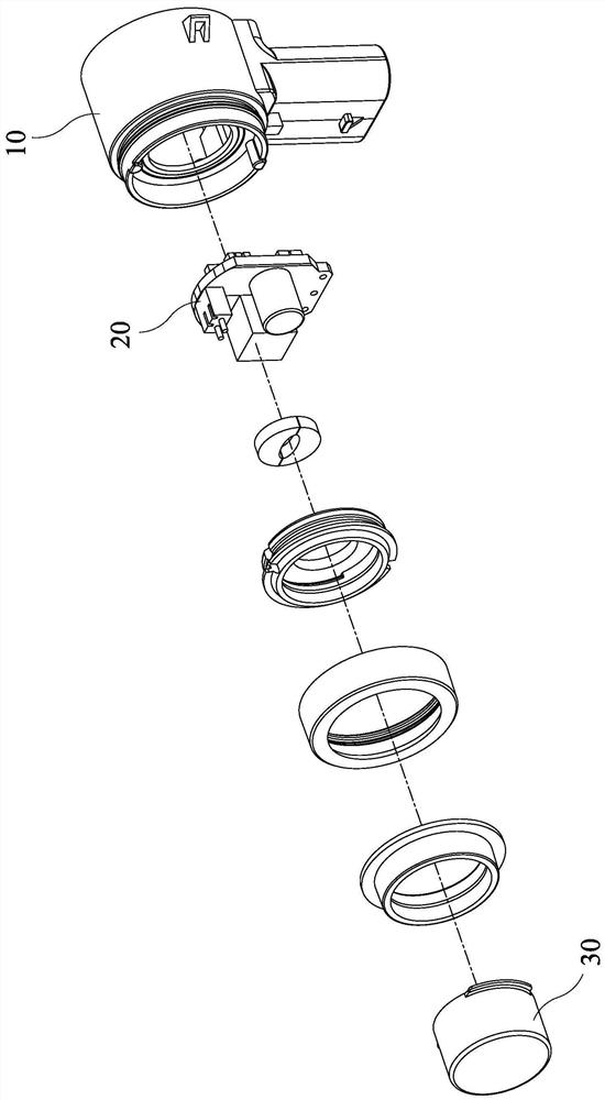
[0034] Aiming at the short-distance blind area problem existing in the existing ultrasonic probe, the present invention proposes an ultrasonic probe that can effectively receive echo signals within the after-vibration time, such as figure 1 As shown, the ultrasonic probe includes a terminal base 10 , a circuit board 20 and a detector 30 , wherein the detector 30 is connected to the circuit board 20 and is arranged on the terminal base 10 together with the circuit board 20 . The circuit board 20 of the ultrasonic probe generates a driving signal, which is sent to the detector 30, and the detector 30 receives the driving signal and emits ultrasonic waves, and at the same time, the detector 30 also receives the echo and converts the echo into electrical The signal is sent to the circuit board 20 for processing. The reason why the ultrasonic probe can transmit and receive ultrasonic waves at the same time is that the present invention improves the detector 30 .

[0035] Specifica...


PUM


Abstract

The invention relates to a detector and an ultrasonic probe structure. The detector comprises a shell, a first transducer and a second transducer, the first transducer and the second transducer are arranged on the shell, the first transducer is used for transmitting or receiving ultrasonic waves, and the second transducer is used for transmitting or receiving the ultrasonic waves; and a gap is formed between the first transducer and the second transducer. According to the detector, the ultrasonic probe is improved at the detector end, so that the ultrasonic probe can emit and receive the ultrasonic waves at the same time, the problem of a close-range blind area is effectively solved, and full-range detection is realized.

Description

technical field [0001] The invention relates to the technical field of ultrasonic probes, in particular to a detector and an ultrasonic probe structure. Background technique [0002] Ultrasonic probes use piezoelectric ceramics as transducers to transmit and receive ultrasonic waves. A certain super-audio signal is applied to the piezoelectric ceramic sheet of the probe, and the piezoelectric ceramic sheet converts electrical energy into sound energy and sends ultrasonic waves. When the echo is received, the echo acts on the piezoelectric ceramic sheet of the probe, and the piezoelectric ceramic sheet converts the sound energy into an electrical signal, and the weak electrical signal is sent to the circuit for processing after being amplified. [0003] The key component of the ultrasonic probe to realize piezoelectric conversion is the detector. After each ultrasonic vibration is emitted, due to its inherent characteristics, the detector will maintain vibration for a period...

Claims


Application Information

Patent Timeline
Patent Type & Authority Applications(China)
IPC IPC(8): B06B1/06
CPCB06B1/0607
Inventor 辜祖敏周玉龙李春娘许鹏伟
Owner TUNG THIH ELECTRONICS (XIAMEN) CO LTD
Why Eureka
Try Eureka