LED visible light communication system and light receiving antenna

A light-receiving antenna and visible light communication technology, applied in the field of optical communication, can solve problems such as limited size, poor light-receiving performance, and high price, and achieve the effects of short response time, reduced volume, and improved sensitivity

Inactive Publication Date: 2013-03-06
KUANG CHI INST OF ADVANCED TECH +1
View PDF3 Cites 21 Cited by
  • Summary
  • Abstract
  • Description
  • Claims
  • Application Information

AI Technical Summary

Problems solved by technology

[0004] The technical problem to be solved by the present invention is to provide an LED visible light communication system and a light receiving antenna for the defects of the prior art such as limited size, high price, and poor light receiving performance.

Method used


Image

  • LED visible light communication system and light receiving antenna
  • LED visible light communication system and light receiving antenna
  • LED visible light communication system and light receiving antenna

Examples


Embodiment Construction

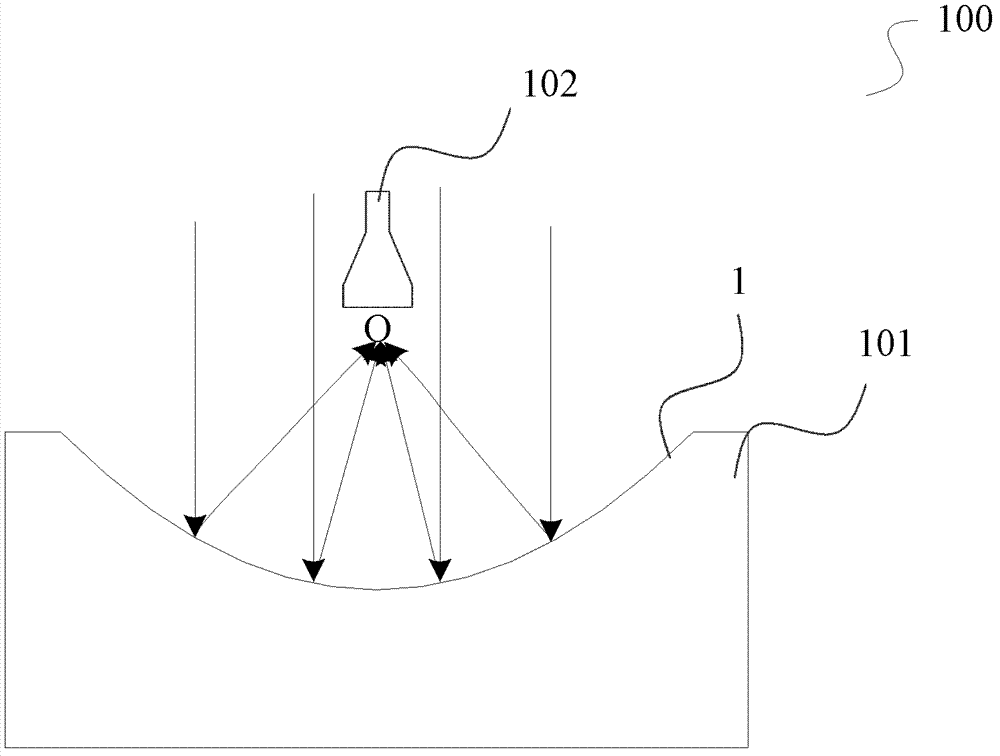
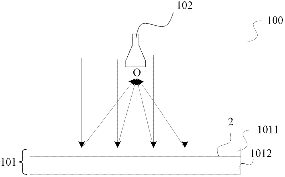
[0023] figure 1 It is a structural schematic diagram of a light-receiving antenna for an LED visible light communication system according to an embodiment of the present invention. The light-receiving antenna 100 includes a converging and reflecting unit 101 having functions of converging and reflecting, and a photodetector 102 located at the focal point of the converging and reflecting unit 101 .

[0024] The converging and reflecting unit 101 is used for converging the optical signal carrying the communication information emitted by the LED light source in the LED visible light communication system 100 to the focal point O, so that the optical signal is received and analyzed by the photodetector 102 to restore the communication information.

[0025] exist figure 1 In the illustrated embodiment, the converging reflective unit 101 is a reflective mirror whose reflective surface is a paraboloid. The reflective mirror can be made of, for example, glass or polymeric material, ...


PUM


Abstract

The invention relates to an LED visible light communication system and a light receiving antenna. The light receiving antenna comprises a converging and reflecting unit with converging and reflecting functions and a photoelectric detector arranged at a focal point of the converging and reflecting unit, wherein the converging and reflecting unit is used for converging light signals which are transmitted by an LED light source and carry communication information at the focal point, so that the photoelectric detector receives and analyzes the light signals and recovers the communication information. The light receiving antenna has the beneficial effects that convergence and reception of the light signals are achieved by the light receiving antenna, thus recovering the communication information carried in the light signals transmitted by the LED light source and achieving LED visible light communication; the reflective mirror with the reflecting surface being a paraboloid is adopted as the converging and reflecting unit, thus being capable of easily expanding the light receiving area, achieving large-range light receiving, being beneficial to detection of dim light, improving the sensitivity, avoiding impact of surrounding stray light and ensuring good anti-jamming effect; and a Fresnel prism is adopted to achieve reflection and convergence of light and convergence of reflective light with the help of a reflecting plate, thus reducing the volume of the receiving antenna.

Description

technical field [0001] The present invention relates to optical communication technology, more specifically, to an LED visible light communication system and a light receiving antenna. Background technique [0002] Visible light LED has excellent characteristics such as high brightness, high reliability, low energy loss and long life, and can be used for display, lighting, traffic signal indication, etc. While visible light LED is used for lighting, it has many advantages as a signal light source to realize wireless communication. [0003] The light-receiving antenna is one of the key problems to be solved in the visible light LED wireless communication system, which is usually composed of a convex lens and a photodetector placed at the focal point. The light-receiving antenna with a simple structure can have high light-receiving efficiency when the signal light is vertically incident, but when the signal light is obliquely incident, the signal light will be defocused and o...

Claims


Application Information

Patent Timeline
Patent Type & Authority Applications(China)
IPC IPC(8): H04B10/116
Inventor 刘若鹏栾琳刘京京马伟涛许学君
Owner KUANG CHI INST OF ADVANCED TECH
Why Eureka
Try Eureka