

Stamping equipment and stamping method for oil pump cover machining
A technology of stamping equipment and pump cover, which is applied to the stamping equipment and field of stamping for oil pump pump cover processing, which can solve the problems of increased demand, waste of resources, work efficiency, and reduction
- Summary
- Abstract
- Description
- Claims
- Application Information
AI Technical Summary
Problems solved by technology
Method used
Image

Examples
Embodiment 1
[0040] A stamping method for processing an oil pump pump cover, the steps are as follows:
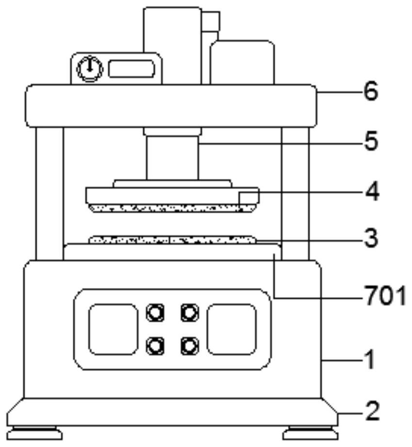
[0041] S1: Before stamping, check the stamping equipment, the upper mold 4 and the lower mold 3, record the wear of the inner wall of the stamping mold and the blade, and replace them in time, and then complete the preparation for the stamping process;
[0042] S2: On the basis of S1, evenly drop 20% lubricating oil along the side wall of the lower mold 3 of the stamping equipment to reduce the wear rate and reduce the generation of burrs;
[0043] S3: On the basis of S2, start the second electric turntable 802 to drive the push rod 805 to rotate, and then drive the sleeve rod 804 to move upward. When the sleeve rod 804 moves to the highest point, the clamping column 808 enters the interior of the arc groove 809 , and then it is stuck, and the user then picks and places materials on the lower mold 3;
[0044] S4: On the basis of S3, the second electric turntable 802 continues to drive ...
Embodiment 2
[0049] A stamping method for processing an oil pump pump cover, the steps are as follows:
[0050] S1: Before stamping, check the stamping equipment, the upper mold 4 and the lower mold 3, record the wear of the inner wall of the stamping mold and the blade, and replace them in time, and then complete the preparation for the stamping process;
[0051] S2: On the basis of S1, evenly drop 25% lubricating oil along the side wall of the lower mold 3 of the stamping equipment to reduce the wear rate and reduce the generation of burrs;
[0052] S3: On the basis of S2, start the second electric turntable 802 to drive the push rod 805 to rotate, and then drive the sleeve rod 804 to move upward. When the sleeve rod 804 moves to the highest point, the clamping column 808 enters the interior of the arc groove 809 , and then it is stuck, and the user then picks and places materials on the lower mold 3;
[0053] S4: On the basis of S3, the second electric turntable 802 continues to drive ...
Embodiment 3
[0058] A stamping method for processing an oil pump pump cover, the steps are as follows:
[0059] S1: Before stamping, check the stamping equipment, the upper mold 4 and the lower mold 3, record the wear of the inner wall of the stamping mold and the blade, and replace them in time, and then complete the preparation for the stamping process;
[0060] S2: On the basis of S1, evenly drop 30% lubricating oil along the side wall of the lower mold 3 of the stamping equipment to reduce the wear rate and reduce the generation of burrs;
[0061] S3: On the basis of S2, start the second electric turntable 802 to drive the push rod 805 to rotate, and then drive the sleeve rod 804 to move upward. When the sleeve rod 804 moves to the highest point, the clamping column 808 enters the interior of the arc groove 809 , and then it is stuck, and the user then picks and places materials on the lower mold 3;
[0062] S4: On the basis of S3, the second electric turntable 802 continues to drive ...
PUM
 Abstract
Description
Claims
Application Information