Pipe drawing lubrication device and pipe drawing processing method

A technology for pipe drawing and processing methods, which is applied in quantitative devices, lubricating parts, lubricating oil control valves, etc., can solve the problems of uneven lubricating oil addition, low production efficiency, and lack of lubricating oil, and achieves good automatic control effect. , The effect of improving the quality of the inner surface and improving the lubrication conditions

Active Publication Date: 2020-06-16
西安诺博尔稀贵金属材料股份有限公司
View PDF5 Cites 0 Cited by
  • Summary
  • Abstract
  • Description
  • Claims
  • Application Information

AI Technical Summary

Problems solved by technology

The lubrication method adopted in the existing drawing process is: manually inject lubricating oil into the inside of the tube blank to be drawn, and then install the drawing core for drawing. However, this lubrication method has the following disadvantages: 1. Due to the The drawn pipe is laid horizontally during drawing, so when liquid lubricating oil is used, the lubricating oil inside the pipe to be drawn will flow along the inner wall of the pipe to be drawn to the bottom of the pipe to be drawn, causing the inner wall of the pipe to be drawn to The lubricating oil is added unevenly, and the local lubricating oil on the inner wall of the pipe blank to be drawn is missing; 2. During the drawing process, the lubricating oil cannot be continuously injected, and a large amount of lubricating oil will flow out from the tail end of the pipe to be drawn. 3. When manually injecting lubricating oil, there is a risk of scratching the surface of the inner wall of the pipe to be drawn, and the production efficiency is low; in order to solve the above technical problems, a pipe drawing lubrication device and a pipe drawing processing method are now proposed

Method used


Image

  • Pipe drawing lubrication device and pipe drawing processing method
  • Pipe drawing lubrication device and pipe drawing processing method
  • Pipe drawing lubrication device and pipe drawing processing method

Examples


Embodiment 1

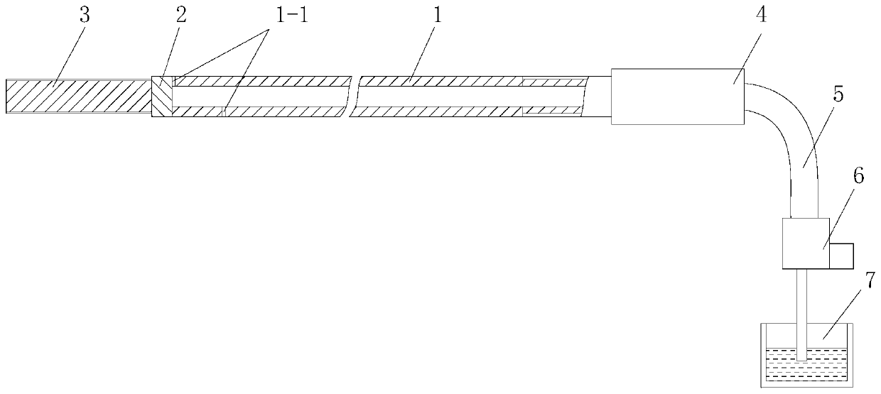
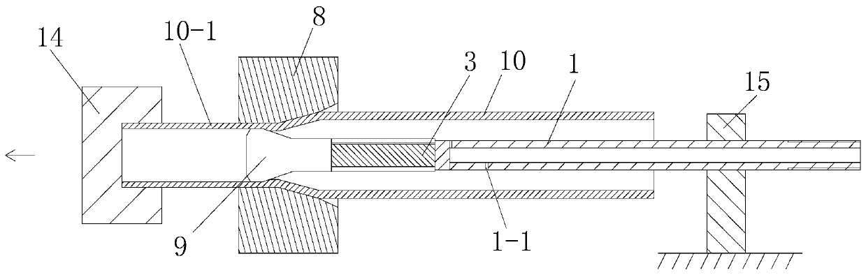
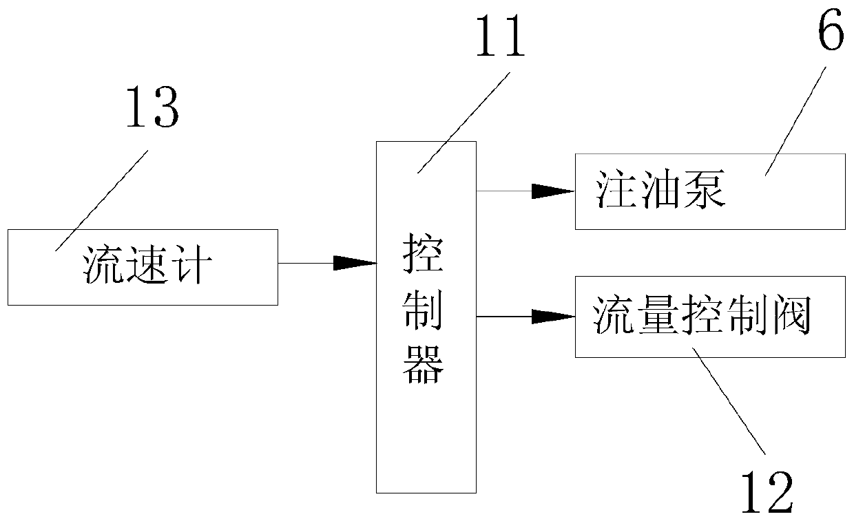
[0048] Such as figure 1 , figure 2 with image 3 As shown, a lubricating device for pipe drawing provided by the present invention includes an oil supply mechanism arranged on a chain broaching machine and a lubricating pipe connected to the oil supply mechanism, and the oil supply mechanism includes an oil tank for holding lubricating oil 7. The oil injection pipe 5 connected to the lubrication pipe and the oil injection pump 6 connected between the oil tank 7 and the oil injection pipe 5. The lubrication pipe is composed of a straight steel pipe 1, a sealing plate 2 arranged at one end of the straight steel pipe 1 and The connecting rod 3 installed on the end face of the sealing plate 2 and used to connect with the drawing core 9 is composed of the straight steel pipe 1 composed of an oil injection section, a clamping section and a connecting section, and the oil injection section is close to a part of the sealing plate 2 On the side, the pipe wall of the oil injection se...

Embodiment 2

[0063] In this embodiment, the pipe drawing processing method includes the following steps:

[0064] Step 1. Preparation of the tube blank to be drawn:

[0065] Step 101, preparation of raw material tube;

[0066] Step 102, the pretreatment of the raw material tube blank includes the following steps:

[0067] Step 1021, pretreatment of the inner surface of the raw tube blank: using a honing machine to grind the inner surface of the raw tube blank so that the surface roughness of the inner surface of the raw tube blank is 1.6 μm;

[0068] Step 1022, pretreatment of the outer surface of the raw material tube blank: first, seal the openings at both ends of the raw material tube blank with rubber plugs; then, use a coreless grinder to grind the outer surface of the raw material tube blank; then, use an abrasive belt to polish Machine polishing the outer surface of the raw tube blank, so that the surface roughness of the outer surface of the raw tube blank is 0.8 μm;

[0069] St...

Embodiment 3

[0092] In this embodiment, the difference from embodiment 2 is:

[0093] In step 1, the outer diameter of the raw tube blank is 15mm, and the wall thickness of the raw tube blank is 3mm; the surface roughness of the inner surface of the tube blank 10 to be drawn in step a is 1.6um; the outer surface of the tube blank 10 to be drawn in step b is The surface roughness is 0.8um; the length of the elongated section 10-1 is 150mm in the step 103; the cone angle of the frustum-shaped hole described in the step 2 is 27 °; the core head of the drawing core 9 described in the step 3 The gap between the outer surface of the end and the inner surface of the circular tube to be drawn 10 in step 2 is 0.03 mm; is 15mm / s; in step 4, the pipe blank 10 to be drawn is reduced in diameter and wall to form a drawn pipe with an outer diameter of 12mm and a wall thickness of 2.9mm; the set value of the lubricating oil flow rate is 8mm 3 / s.

[0094] In this embodiment, the remaining steps and pro...


PUM

PropertyMeasurementUnit
surface roughnessaaaaaaaaaa
lengthaaaaaaaaaa

Abstract

The invention discloses a pipe pulling and drawing lubricating device, and further discloses a pipe pulling and drawing machining method. The pipe pulling and drawing lubricating device comprises an oil supplying mechanism arranged on a chain broaching machine and a lubricating pipe connected with the oil supplying mechanism. The oil supplying mechanism comprises an oil box for storing lubricatingoil, an oil injecting pipe connected with the lubricating pipe and an oil injecting pump connected to the position between the oil box and the oil injecting pipe. The lubricating pipe is composed ofa flat and straight steel pipe, a sealing plate arranged at one end of the flat and straight steel pipe and a connecting rod mounted on the end face of the sealing plate and used for being connected with a pulling and drawing core head. The flat and straight steel pipe is composed of an oil injecting section, a clamping section and a connecting section. The pipe pulling and drawing machining method comprises the steps of 1, preparation of a to-be-pulled-drawn pipe blank, 2, mounting of a pulling and drawing external mold and the to-be-pulled-drawn pipe blank, 3, mounting of the lubricating device and the pulling and drawing core head, and 4, lubricating and pulling-drawing of the to-be-pulled-drawn pipe blank. According to the pipe pulling and drawing lubricating device, the purpose that the lubricating oil is continuously injected into the pipe blank can be achieved, the phenomena that adding of the lubricating oil is uneven, and the local lubricating oil of the inner wall of a pipe is absent cannot occur, and the quality of the inner surface of the pipe after being pulled and drawn is improved.

Description

technical field [0001] The invention relates to a lubricating device and a pipe material production method, in particular to a pipe material drawing lubricating device and a pipe material drawing processing method. Background technique [0002] As one of the common methods of pipe preparation, the drawing process is widely used in the industrial production of copper pipes and stainless steel pipes. The equipment used in the drawing process is mainly a chain broaching machine. By installing the drawing die on the chain broaching machine , the drawing die includes the drawing outer die and the drawing core head. Compared with the traditional rolling process, the drawing process of the pipe has the following advantages: it can improve the dimensional accuracy of the outer diameter and wall thickness of the pipe, and for the smaller diameter The high-quality pipe can achieve wall-reducing stretching, improve the quality of the inner surface of the pipe, and improve the distribut...

Claims


Application Information

Patent Timeline
Patent Type & Authority Patents(China)
IPC IPC(8): B21C3/14
CPCB21C9/00F16N7/38F16N21/00F16N23/00F16N27/00F16N29/02
Inventor 邢健陈昊周龙海沈大吉孙海霞韩军李红宇韩吉庆
Owner 西安诺博尔稀贵金属材料股份有限公司
Why Eureka
Try Eureka