Full-automatic numerical control cutting saw for aluminum door and window corner connectors

A fully automatic cutting saw technology, which is applied in the direction of sawing machine, metal sawing equipment, metal processing equipment, etc. It can solve the problem of low processing accuracy of corner codes, corner codes that cannot be completely fixed, and angles between corner codes that are difficult to present at 90 degrees. and other issues to achieve the effect of reducing shaking

Active Publication Date: 2021-08-13
SICHUAN QINGCHUAN CONSTR ENG
View PDF11 Cites 0 Cited by
  • Summary
  • Abstract
  • Description
  • Claims
  • Application Information

AI Technical Summary

Problems solved by technology

[0003] In the related technology, the Chinese patent whose notification number is CN207857968U discloses a kind of automatic corner code saw for aluminum doors and windows. figure 1 discloses a tapered block used to abut against the angle of the corner code, which is used to abut against the corner code when the corner code is cut, so as to reduce the shaking of the aluminum profile during processing. However, due to the processing accuracy of the corner code, the clamping angle of the corner code It is difficult to present a 90-degree angle, and with the emergence of non-right-angled corners, the tapered block in this application cannot fully adapt to the angle between the corners. The defect of low machining accuracy

Method used


Image

  • Full-automatic numerical control cutting saw for aluminum door and window corner connectors
  • Full-automatic numerical control cutting saw for aluminum door and window corner connectors
  • Full-automatic numerical control cutting saw for aluminum door and window corner connectors

Examples


Embodiment Construction

[0029] The following is attached Figure 1-3 The application is described in further detail.

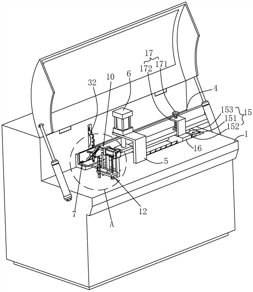
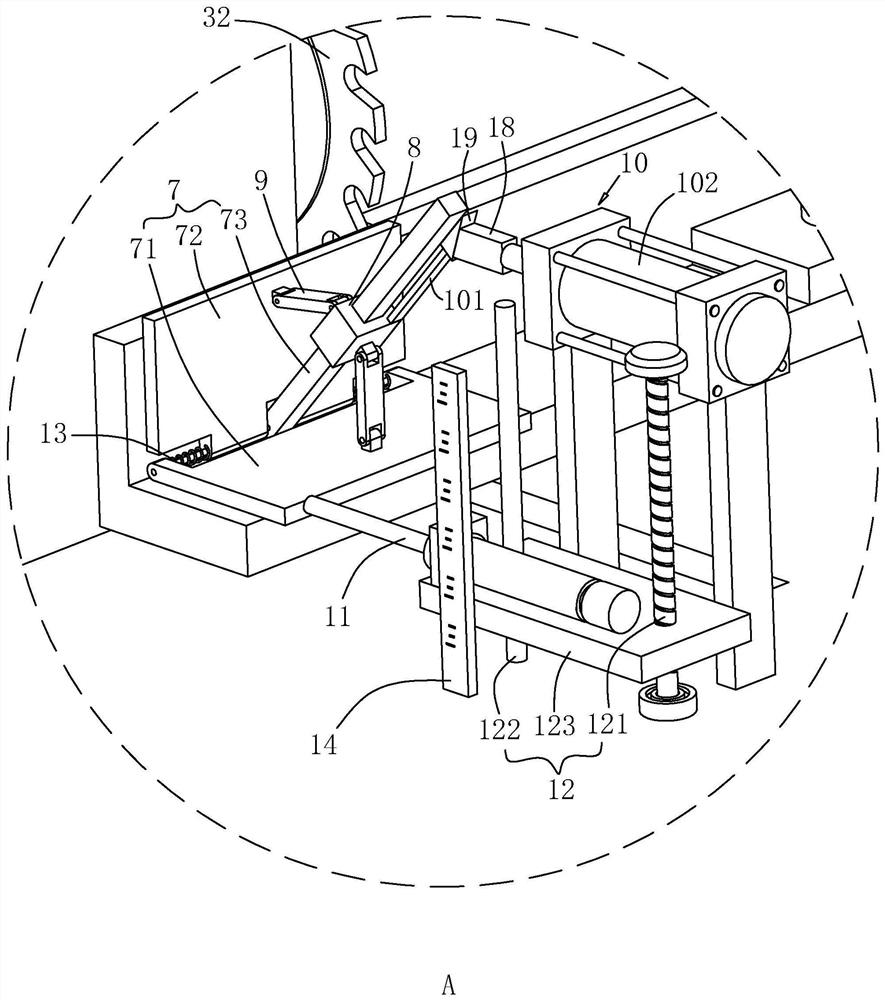
[0030]The embodiment of the present application discloses a fully automatic numerical control cutting saw for aluminum door and window corners. refer to figure 1 , the aluminum door and window corner code automatic numerical control cutting saw includes a workbench 1, and the workbench 1 is welded with a baffle plate 4 for abutting the profile along the feeding direction of the profile. The workbench 1 is vertically welded with a pillar 5. In this embodiment, the pillar 5 is L-shaped. The side of the pillar 5 parallel to the workbench 1 is fixedly connected with a down-press cylinder 6 by bolts. The down-press cylinder 6 is connected to the workbench 1. The upper surface is parallel and used to abut against the profile. The workbench 1 is provided with a feeding device 15 for pushing profiles along its length direction, and the feeding device 15 includes a second motor 151 , a sec...


PUM


Abstract

The invention relates to a full-automatic numerical control cutting saw for aluminum door and window corner connectors, which comprises a workbench, wherein a baffle plate used for abutting against a profile is arranged on the workbench in the feeding direction of the profile, an abutting piece used for abutting against an inner included angle of the profile is arranged on the workbench in the direction perpendicular to the feeding direction of the profile, and the abutting piece comprises a first abutting plate, a second abutting plate and a supporting rod; the supporting rod is sleeved with and slidably connected with a sleeve, the sleeve is rotationally connected with two connecting rods, the end, away from the sleeve, of one connecting rod is rotationally connected with the first abutting plate, the end, away from the sleeve, of the other connecting rod is rotationally connected with the second abutting plate, and a fastener used for fixing the sleeve is arranged on the supporting rod; and the first abutting plate is parallel to the upper surface of the workbench, and a second driving piece used for driving the first abutting plate to reciprocate in the direction perpendicular to the sectional material feeding direction is arranged on the workbench. The full-automatic numerical control cutting saw has the effect of conveniently fixing the profile during corner connector machining.

Description

technical field [0001] The present application relates to the field of corner code cutting technology, in particular to a fully automatic numerical control cutting saw for corner codes of aluminum doors and windows. Background technique [0002] At present, in architecture, the corner bracket is the hardware that connects the intersecting components at 90 degrees, and the corner bracket of aluminum doors and windows refers to the connecting piece of the aluminum alloy door leaf and the outer frame. The cutting saw is a cutting device used to cut corners when producing aluminum doors and windows. [0003] In the related technology, the Chinese patent whose notification number is CN207857968U discloses a kind of automatic corner code saw for aluminum doors and windows. figure 1 discloses a tapered block used to abut against the angle of the corner code, which is used to abut against the corner code when the corner code is cut, so as to reduce the shaking of the aluminum profi...

Claims


Application Information

Patent Timeline
IPC IPC(8): B23D45/02B23D47/04B23D47/10
CPCB23D45/022B23D47/04B23D47/10Y02P70/10
Inventor 谭宁温仕强范绪泉
Owner SICHUAN QINGCHUAN CONSTR ENG
Why Eureka
Try Eureka