
Clamping device for metal machining

A clamping device and metal processing technology, used in metal processing equipment, metal processing mechanical parts, positioning devices, etc., can solve the problems of affecting the processing accuracy of parts, single fixing method, low fixing strength, etc., to improve practicability, simplify Manpower, the effect of improving stability

Active Publication Date: 2021-08-13
WEIFANG BUSINESS VOCATIONAL COLLEGE
View PDF7 Cites 4 Cited by
  • Summary
  • Abstract
  • Description
  • Claims
  • Application Information

AI Technical Summary

Problems solved by technology

[0002] As we all know, when metal parts are processed, they usually need to be clamped and fixed, so as to avoid the movement of the firmware during processing and affect the processing accuracy, especially for tubular metal parts, because such metal parts are easy to rotate during processing Slip phenomenon, which has higher requirements on the clamping device. The existing metal parts clamping method is usually fixed by cylinder or tie rod. However, this kind of fixing method is relatively simple, and its fixing strength is low. When it is easy to shift, it will affect the machining accuracy of the parts

Method used


Image

  • Clamping device for metal machining
  • Clamping device for metal machining
  • Clamping device for metal machining

Examples


Embodiment Construction

[0030] The following will clearly and completely describe the technical solutions in the embodiments of the present invention with reference to the accompanying drawings in the embodiments of the present invention. Obviously, the described embodiments are only some, not all, embodiments of the present invention.

[0031] In the description of the present invention, it should be noted that the terms belonging to "center", "upper", "lower", "left", "right", "vertical", "horizontal", "inner", "outer" etc. The indicated orientation or positional relationship is based on the orientation or positional relationship shown in the drawings, and is only for the convenience of describing the present invention and simplifying the description, rather than indicating or implying that the referred device or element must have a specific orientation, or in a specific orientation. construction and operation, therefore, should not be construed as limiting the invention.

[0032] In the descriptio...


PUM


Abstract

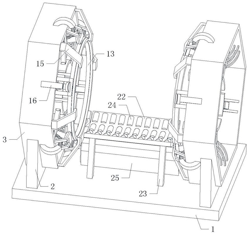
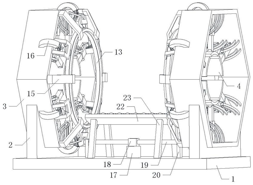
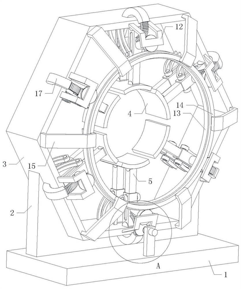
The invention relates to the technical field of clamping tools, in particular to a clamping device for metal machining. The clamping device comprises a base, two installing plates are symmetrically arranged on the base, polygonal outer frames are arranged on the installing plates, a plurality of arc-shaped clamping plates are annularly and uniformly distributed inside the polygonal outer frame, and the number of the arc-shaped clamping plates corresponds to that of the edges of the polygonal outer frame. According to the structure, the clamping strength of a metal part can be effectively improved, the stability of the metal part during machining is improved, the situation that the part moves and influences the machining precision is avoided, meanwhile, the equipment can automatically clamp the part, manpower during manual operation is simplified, and practicability is improved.

Description

technical field [0001] The invention relates to the technical field of clamping tooling, in particular to a clamping device for metal processing. Background technique [0002] As we all know, when metal parts are processed, they usually need to be clamped and fixed, so as to avoid the movement of the firmware during processing and affect the processing accuracy, especially for tubular metal parts, because such metal parts are prone to rotation during processing Slipping phenomenon, which has higher requirements on the clamping device, the existing metal parts clamping method is usually fixed by cylinder or tie rod, but this kind of fixing method is relatively simple, its fixing strength is low, and the metal parts are subjected to external force When it is easy to shift, it will affect the machining accuracy of the parts. Contents of the invention [0003] In order to solve the above technical problems, the present invention provides a clamping device for metal processing...

Claims


Application Information

Patent Timeline
Patent Type & Authority Applications(China)
IPC IPC(8): B23Q3/06
CPCB23Q3/06B23Q3/064
Inventor 江淑红李冰王娟
Owner WEIFANG BUSINESS VOCATIONAL COLLEGE
Learn More