Clamping device with screw rod

A clamping device and a technology with wires, which are applied in the field of mechanical processing fixtures, can solve problems such as insufficient processing accuracy, insufficient clamping strength, and small clamping force, and achieve the goals of improving processing accuracy, wide application range, and reducing vibration. Effect

Inactive Publication Date: 2016-04-06
CHONGQING YIYAO TECH CONSULTATION CO LTD
View PDF5 Cites 2 Cited by
  • Summary
  • Abstract
  • Description
  • Claims
  • Application Information

AI Technical Summary

Problems solved by technology

The existing milling machine clamping tool has complex structure, small clamping force, and insufficient clamping strength, resulting in large vibration during milling and insufficient machining accuracy. Solving the above problems has become a top priority

Method used


Image

  • Clamping device with screw rod

Examples


Embodiment Construction

[0014] The present invention will be further described below in conjunction with the embodiments and accompanying drawings.

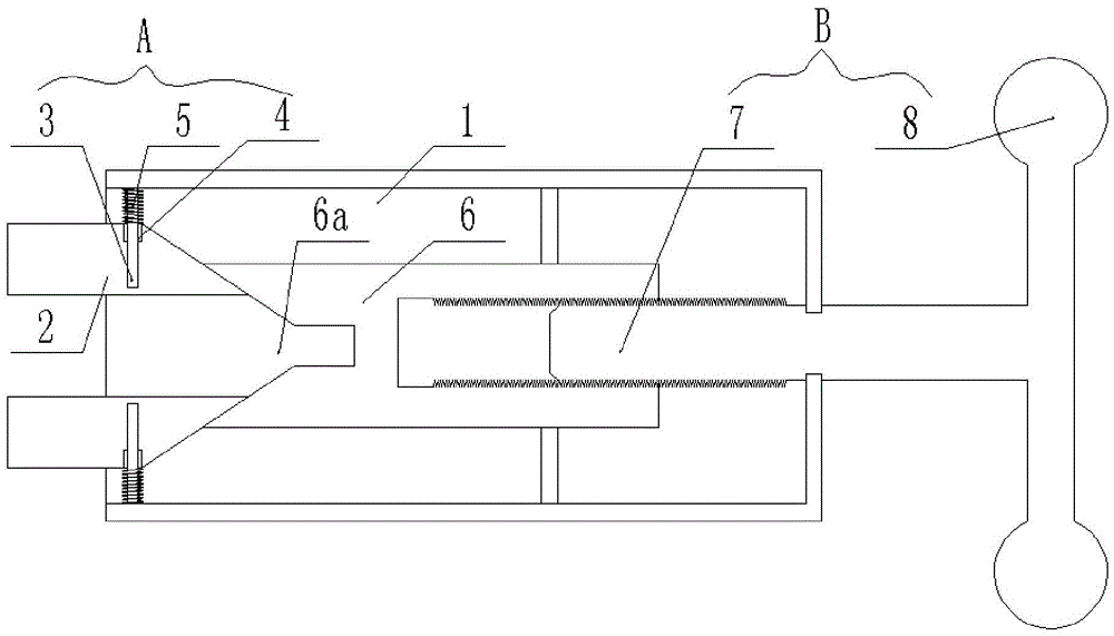
[0015] Such as figure 1 As shown, a clamping device with a screw rod includes a mounting cavity 1, and two clamping arms 2 facing oppositely are installed in the mounting cavity 1, and the heads of the clamping arms 2 respectively face The front protrudes from the installation cavity 1, and two reset guides A are installed in the installation cavity 1, and the reset guides A are respectively connected to one of the clamping arms 2. A clamping arm internal pressure rod 6 is provided in the cavity 1, and the front end of the clamping arm internal pressure rod 6 is aligned with the tail of the clamping arm 2, that is, the tails of the two clamping arms 2 face toward the The direction of the clamping arm internal pressure rod 6 gradually decreases from the outside to the inside, and the front end of the clamping arm internal pressure rod 6 is provided with...


PUM


Abstract

The invention discloses a clamping device with a screw rod. The clamping device comprises an installation cavity, wherein two clamping arms facing each other directly are installed inside the installation cavity; heads of the clamping arms protrude forwards and extend out of the installation cavity; two resetting and guiding devices facing each other directly are installed inside the installation cavity; the resetting and guiding devices are connected with one of the clamping arms respectively; an internal pressure rod for the clamping arms is arranged inside the installation cavity; the front end of the internal pressure rod for the clamping arms is aligned with the tail of the clamping arms; when the internal pressure rod for the clamping arms move forwards, the internal pressure rod drives the clamping arms to clamp each other relatively; the internal pressure for the clamping arms is driven by a jacking device; each resetting and guiding device comprises a guiding sliding block, a sliding block and a resetting tension spring; and the jacking device comprises the screw rod and a rotating handle. With the adoption of the structure, the application range is wide, and the operation is simple; the clamping strength is high; the vibration of an original component during milling is reduced; and the milling accuracy is effectively improved.

Description

technical field [0001] The invention belongs to the field of machining fixtures, and in particular relates to a clamping device with a screw rod. Background technique [0002] The clamping tool is the device used to fix the processing object in the process of mechanical manufacturing so that it occupies the correct position to accept construction or inspection. [0003] During milling, the cutting force is large, and the cutting is intermittent, and the vibration is large. Therefore, the clamping force of the milling machine fixture is required to be large, and the rigidity and strength of the fixture are relatively high. The existing milling machine clamping tool has complex structure, small clamping force and insufficient clamping strength, resulting in large vibration during milling and insufficient machining accuracy. Solving the above problems has become a top priority. Contents of the invention [0004] In order to solve the above technical problems, the present inv...

Claims


Application Information

Patent Timeline
Patent Type & Authority Applications(China)
IPC IPC(8): B23Q3/06
CPCB23Q3/062
Inventor 王怡
Owner CHONGQING YIYAO TECH CONSULTATION CO LTD
Why Eureka
Try Eureka