Steer-by-wire device with redundancy function and control method

A steering-by-wire, functional technology, applied in automatic steering control components, steering mechanisms, steering rods, etc., can solve the problems of low steering safety and single redundant function.

Active Publication Date: 2021-08-13
CHINA FIRST AUTOMOBILE
View PDF12 Cites 0 Cited by
  • Summary
  • Abstract
  • Description
  • Claims
  • Application Information

AI Technical Summary

Problems solved by technology

[0003]However, in the current steer-by-wire devices, only the motors and controllers in the steer-by-wire devices are usually redundantly set, and the redundancy function is relatively simple, which cannot Fully meet the redundancy requirements in the steering process, resulting in low steering safety

Method used


Image

  • Steer-by-wire device with redundancy function and control method
  • Steer-by-wire device with redundancy function and control method
  • Steer-by-wire device with redundancy function and control method

Examples


Embodiment 1

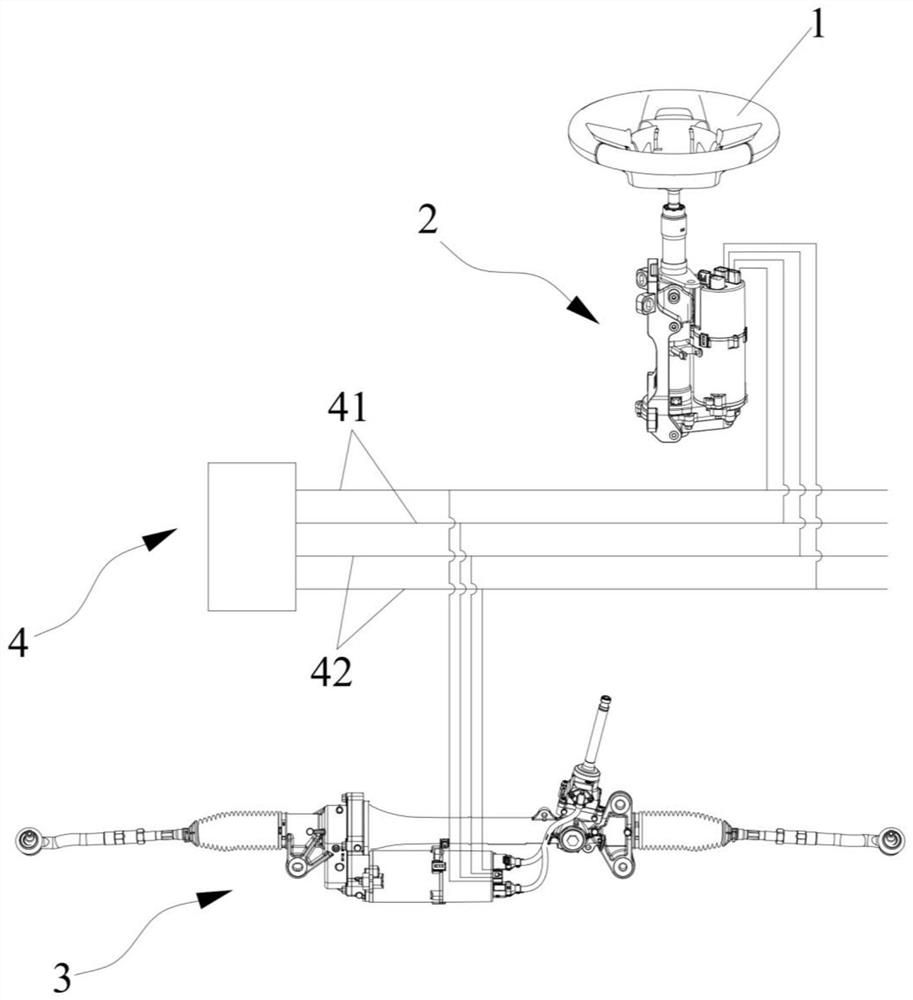
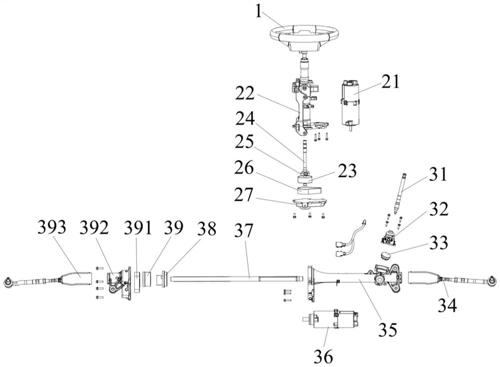
[0057] In this embodiment, a steering-by-wire device with redundant functions is proposed, which can avoid the failure of the steering ability of the entire steering-by-wire device with redundant functions and the failure of the driver's sense of road when it fails, Its redundant functions are relatively complete, making its steering safer.

[0058] Specifically, such as Figure 1-5 As shown, the steer-by-wire device with redundant functions includes a steering wheel 1 , a road feeling simulator 2 and a steering actuator 3 . Wherein, the road feeling simulator 2 includes a first control module 21, a torsion bar 24, and a torque angle sensor 25 arranged on the torsion bar 24, and the first control module 21 includes a first motor 212 and a first motor 212 for controlling the first motor 212. A controller 211, a second motor 214 and a second controller 213 for controlling the second motor 214, the torsion bar 24 is connected to the steering wheel 1, the first controller 211 and...

Embodiment 2

[0072] In this embodiment, a control method based on the steering-by-wire device with redundant functions in Embodiment 1 is proposed, which includes the following steps:

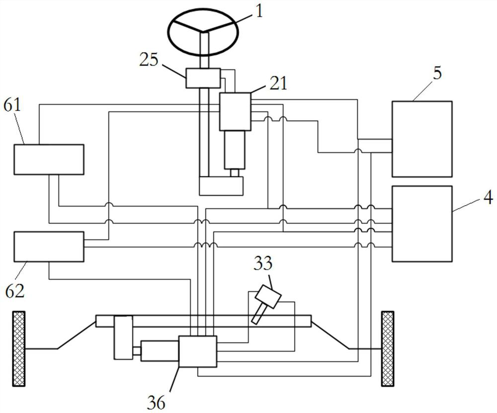
[0073] S10: The first power supply 61 supplies power to the first controller 211, the third controller 361 and the first communication line 41 respectively, and the second power supply 62 is respectively connected to the second controller 213, the fourth controller 363 and the second communication line 42 power supply;

[0074] S20: The first ignition switch 51 provides ignition signals to the first controller 211 and the third controller 361 respectively, and the second ignition switch 52 provides ignition signals to the second controller 213 and the fourth controller 363 respectively;

[0075] S30: the first controller 211 receives the signal of the torque angle sensor 25 and the network signal of the first communication line 41; at the same time, the second controller 213 receives the signal of the torqu...


PUM


Abstract

The invention discloses a steer-by-wire device with a redundancy function and a control method, and belongs to the technical field of steer-by-wire. The steer-by-wire device with the redundancy function comprises a steering wheel; the road feeling simulator comprises a first control module, a torsion bar and a torque angle sensor arranged on the torsion bar, the first control module comprises a first motor, a first controller, a second motor and a second controller, the torsion bar is connected with the steering wheel, and the first controller is in communication connection with the second controller; a steering actuator comprises a second control module, a rack and a steering angle sensor, the second control module comprises a third motor, a third controller, a fourth motor and a fourth controller, and the third controller is in communication connection with the fourth controller; a whole vehicle gateway comprises a first communication line and a second communication line which are in communication connection with each other; a power supply assembly comprises a first power supply and a second power supply; an ignition assembly comprises a first ignition switch and a second ignition switch. The device has the beneficial effect of high steering safety.

Description

technical field [0001] The invention relates to the technical field of steering-by-wire, in particular to a steering-by-wire device with redundant functions and a control method. Background technique [0002] The steer-by-wire device is widely used because of its good steering comfort, compact structure, and its angular transmission ratio can better adapt to the driving habits of different drivers. Among them, in order to avoid the failure of the steering ability of the entire steering-by-wire device and the failure of the driver's sense of road due to the failure of the steering-by-wire device, it is usually necessary to set a redundant mechanism in the steering-by-wire device to make it redundant. function, thus being able to provide an alternate steering function to improve steering safety. [0003] However, in current steer-by-wire devices, only the motors and controllers in the steer-by-wire device are usually redundantly set, and the redundancy function is relatively ...

Claims


Application Information

Patent Timeline
Patent Type & Authority Applications(China)
IPC IPC(8): B62D5/04B62D6/00B62D7/20B62D119/00B62D113/00
CPCB62D5/0463B62D5/0403B62D5/0406B62D6/00B62D7/20
Inventor 姜廷龙高尚常秀岩侯慧贤
Owner CHINA FIRST AUTOMOBILE
Why Eureka
Try Eureka