A Wellhead Gate Valve with an Automatic Replacement Mechanism for a Pressurized Casing

An automatic replacement and casing technology, which is applied in the direction of sliding valves, engine components, wellbore/well valve devices, etc., can solve the problems of difficult casing disassembly and replacement, and achieve easy replacement, improved sealing effect, and guaranteed The effect of purity

Active Publication Date: 2021-12-24
东营悦来湖园区运营管理有限公司
View PDF0 Cites 0 Cited by
  • Summary
  • Abstract
  • Description
  • Claims
  • Application Information

AI Technical Summary

Problems solved by technology

[0005] The purpose of the present invention is to provide a wellhead gate valve with a pressure casing automatic replacement mechanism, the joint is initially sealed by the sealing ring, and the annular sealing air bag is used for secondary sealing of the connection, which significantly improves the valve body and casing. The sealing effect of the connection between the two joints can prevent oil from leaking out from the joint. The positioning insert rod is inserted into the positioning slot to realize the fixing of the sleeve joint. air pressure, thereby changing the air pressure in the ring-shaped sealed air bag and the cavity, which facilitates the replacement of the bushing, without the need for manual replacement with the help of related tools. The adjustment of the oil speed, the oil is filtered through the filter mechanism, and the impurities in the oil are filtered out to ensure the purity of the oil, which solves the problem that the valve body of the existing wellhead gate valve and the pressurized casing on both sides are generally integrated. Difficulty in removing and replacing the pressurized bushing

Method used


Image

  • A Wellhead Gate Valve with an Automatic Replacement Mechanism for a Pressurized Casing
  • A Wellhead Gate Valve with an Automatic Replacement Mechanism for a Pressurized Casing
  • A Wellhead Gate Valve with an Automatic Replacement Mechanism for a Pressurized Casing

Examples


Embodiment 1

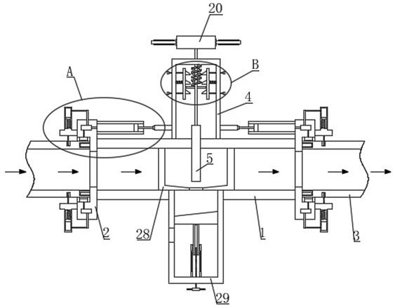
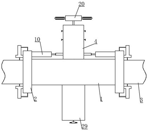
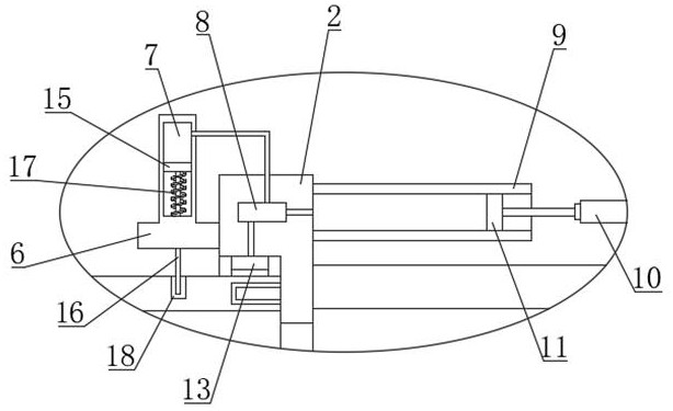
[0035] like Figure 1-8 As shown in the figure, a wellhead gate valve with an automatic replacement mechanism for casing under pressure proposed by the present invention includes a valve body 1, a mounting plate 2, a casing joint 3, an upper valve pipe 4, a valve plate 5 and a lower valve pipe 29, The top of the valve body 1 is fixed with an upper valve pipe 4 by bolts, the bottom of the valve body 1 is fixed with a corresponding lower valve pipe 29 by bolts, and the two ends of the valve body 1 are fixed with a mounting plate 2 by bolts. The joint 3 is connected to the casing, and the mounting plate 2 is provided with a fixed groove 12 and an oil delivery port 14. Oil enters and exits the valve body 1 through the oil delivery ports 14 on both sides. The diameter of the fixed groove 12 is larger than the diameter of the oil delivery port 14. The other end of the pipe joint 3 is inserted into the fixing groove 12 and communicated with the valve body 1 through the oil delivery p...

Embodiment 2

[0041] like Figure 9-10 As shown, this embodiment is basically the same as Embodiment 1. Preferably, a bearing block 34 is slidably arranged in the lower valve pipe 29, and the oil in the valve body 1 enters the oil filter box 30 through the oil inlet 31, and the oil filter hole 32 The oil is filtered, and the filtered debris enters the lower valve pipe 29 through the sewage outlet 33 at the bottom of the oil filter box 30, and the debris falls on the bearing block 34. The bottom of the bearing block 34 is equipped with a lifting mechanism 36. The lifting mechanism 36 For adjusting the height of the bearing block 34, the side wall of the lower valve pipe 29 is provided with a sewage outlet 35. When the bearing block 34 is lowered to the bottom of the sewage outlet 35, the sundries are discharged through the sewage outlet 35, which is convenient for removing the sundries. cleaning, and the upper end of the bearing block 34 is inclined downward in the direction of the sewage ou...

Embodiment 3

[0043] like Figure 6-7 As shown, this embodiment is basically the same as the first embodiment. Preferably, the vertical plate 23 and the upper valve tube 4 are connected by a second spring 26. The second spring 26 is arranged horizontally. A guide rod 25 is installed on the side. The other end of the guide rod 25 passes through the upper valve pipe 4 and is connected to the limit block 27. The guide rod 25 can move in the horizontal direction, and the limit block 27 acts as a limit to avoid the guide rod 25 and the limit block 27. The upper valve tube 4 is disengaged, the upper part of the stopper 24 is an inclined plane, the bottom of the stopper 24 is a horizontal plane, and the inclined plane is inclined downward toward the direction of the rotating rod 21 . When the downward pressure is directly applied to the pressure plate 20, the connecting plate 22 Pressure is applied to the inclined surface of the block 24 below it, and then the block 24 is pushed to move away from ...


PUM


Abstract

The invention belongs to the technical field of wellhead gate valves, and is used to solve the problem that the valve body of the existing wellhead gate valves and the pressurized casings on both sides are generally integrated, and it is difficult to disassemble and replace the pressurized casings. A wellhead gate valve with a pressure casing automatic replacement mechanism, including a valve body, a mounting plate, a casing joint, an upper valve pipe, a valve plate and a lower valve pipe. The top of the valve body is fixed with an upper valve pipe by bolts; the invention is obvious Improve the sealing effect of the joint between the valve body and the casing joint, avoid oil leakage from the joint, insert the positioning plunger into the positioning slot to realize the fixing of the casing joint, and change the ring sealing air bag and the cavity in the cavity The air pressure is used to facilitate the replacement of the casing. The connecting plate is kept at the height through the blocking of the stopper to realize the adjustment of the oil delivery speed. The oil is filtered through the filter mechanism to ensure the purity of the oil.

Description

technical field [0001] The invention relates to the technical field of wellhead gate valves, in particular to a wellhead gate valve with a pressure casing automatic replacement mechanism. Background technique [0002] An oil well is a hole drilled according to the well layout system of the oil field development plan for the exploitation of oil. The oil rises from the bottom of the well to the wellhead. Generally, after the oil well reaches the oil layer, it is lowered into the oil layer casing, and the casing and the well wall are connected. Inject oil well cement into the annular space between them to maintain the well wall and seal the oil, gas, and water layers. Afterwards, according to the requirements of oil field development, use a perforating gun to open the oil layer to form a channel and lower it into the tubing. From the bottom of the oil well to the wellhead; [0003] The wellhead gate valve is mainly used in the wellhead pipeline. The valve body of the wellhead ...

Claims


Application Information

Patent Timeline
Patent Type & Authority Patents(China)
IPC IPC(8): F16K3/02F16K3/32F16K27/04F16L25/00F16L17/10F16L37/62F16L37/12E21B34/02
CPCF16K3/0209F16K3/32F16K27/044F16L25/009F16L37/62F16L37/12F16L17/10E21B34/02
Inventor 史敬东吴硕聂宇超唐凤芹刘智峰
Owner 东营悦来湖园区运营管理有限公司
Why Eureka
Try Eureka