Automatic hang tag stringing device
A technology of automatic threading and tagging, which is applied in the field of tagging machines, can solve problems such as tag rope positioning and card threading, and achieve the effects of simplified structure, simple structure, and cost reduction
- Summary
- Abstract
- Description
- Claims
- Application Information
AI Technical Summary
Problems solved by technology
Method used
Image
Examples
Embodiment 1
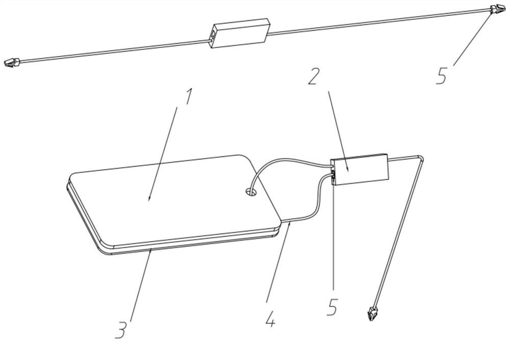
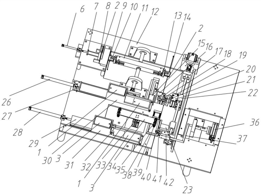
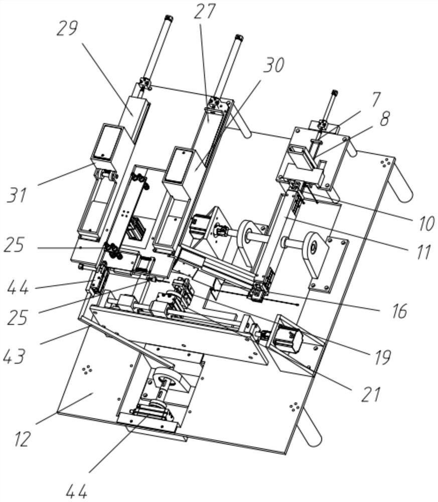
[0029] Such as Figure 1-6 As shown, the buckle groove transmission mechanism provided in this embodiment includes a frame 12, the frame 12 is used to support the whole mechanism, the buckle groove push cylinder 6 is installed on the bed frame 12, and the buckle groove push rod 7 is fixed Connected to the buckle groove pushing cylinder 6, the buckle groove push rod 7 is matched with the buckle groove placement box 8 through the through hole, so that the buckle groove push rod 7 can freely promote the buckle groove. A plurality of snap slots 2 are placed in the snap slot placement box 8, and the snap slot push rod 7 is pushed into the "U"-shaped slot formed by the first clamping auxiliary block 9, and then the first clamping pneumatic finger 10 can Clamp and fix the buckle slot 2, and the buckle slot 2 is rotated 180° by the buckle slot rotation mechanism 11 to move to the next position.
Embodiment 2
[0031] Such as Figure 2-6 As shown, the hang tag card positioning mechanism provided in this embodiment includes a frame 12, the frame 12 is connected with a first push cylinder 26, the first card push rod 27 is installed on the first card push cylinder 26, and is pushed by the first card The push of the cylinder 26 makes the first card push rod 27 push a thick card 1 to the designated position, and then it can be sucked by the vacuum suction cup 35, and multiple thick cards 1 are placed in the first card box 30, and the thick cards 1 are arranged from bottom to top. Promoted by the first card push rod 27 in turn. The second card push cylinder 28 is installed on the frame 12, the second card push rod 29 is installed on the second card push cylinder 30, and the push of the second card push cylinder 28 makes the second card push rod 29 push a plurality of thin cards 3 to the designated position, and then can be sucked by the vacuum chuck 35 from top to bottom. Wherein a plura...
Embodiment 3
[0034] Such as figure 2 , 3 , 5, and 6, the hang tag card delivery device provided in this embodiment includes a first card positioning groove 38, a second card positioning groove 39, a spring 40, a guide rail 41, a card clamping pneumatic finger 42, a card rotating rod 43, Card rotary cylinder 44;
[0035] The thick card 1 and the thin card 3 are all put into the first card positioning groove 38 by the vacuum suction cup 35, the card rotating cylinder 44 is fixedly installed on the frame 12, and the card rotating rod 43 is installed on the card rotating cylinder 44, and along with the card The rotating cylinder 44 moves, and the card clamping pneumatic finger 42 is installed on the card rotating rod 43 and is used to clamp the thick card 1 and the thin card 3. When the card rotating cylinder 44 drives the thick card 1 and the thin card 3 to move, it will push the second card The positioning groove 39 moves, the second card positioning groove moves along the guide rail 41, ...
PUM
 Abstract
Description
Claims
Application Information
 - R&D
- Intellectual Property
- Life Sciences
- Materials
- Tech Scout
- Unparalleled Data Quality
- Higher Quality Content
- 60% Fewer Hallucinations
Browse by: Latest US Patents, China's latest patents, Technical Efficacy Thesaurus, Application Domain, Technology Topic, Popular Technical Reports.
© 2025 PatSnap. All rights reserved.Legal|Privacy policy|Modern Slavery Act Transparency Statement|Sitemap|About US| Contact US: help@patsnap.com


