Prismatoid light guide

A quasi-column and cylinder technology, applied in the field of positron emission tomography, can solve the problems of Anger logic positioning degradation, poor light sharing, few shared crystals and pixels, etc.

Pending Publication Date: 2021-08-13
THE RES FOUND OF STATE UNIV OF NEW YORK
View PDF0 Cites 0 Cited by
  • Summary
  • Abstract
  • Description
  • Claims
  • Application Information

AI Technical Summary

Problems solved by technology

Due to the poor light sharing of conventional uniform light guides, the Anger logic positioning at the periphery of the detector array is severely degraded compared to centralized crystals and detectors, because the peripheral crystals have less shared crystals and pixels

Method used


Image

  • Prismatoid light guide
  • Prismatoid light guide
  • Prismatoid light guide

Examples


Embodiment Construction

[0030] Some embodiments of the present invention will be described in detail below with reference to the accompanying drawings. When describing the present invention, for the sake of clarity, descriptions of related functions or structures known in the art are omitted to avoid obscuring the present invention with unnecessary details.

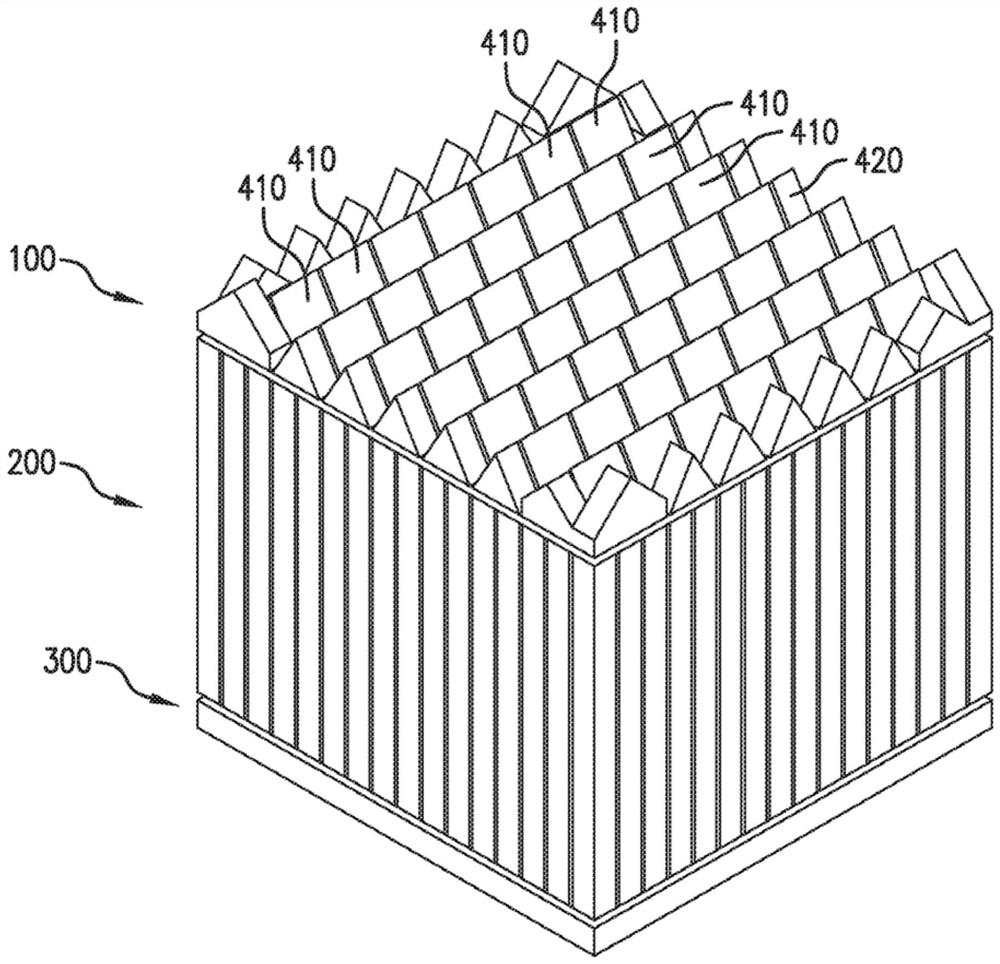
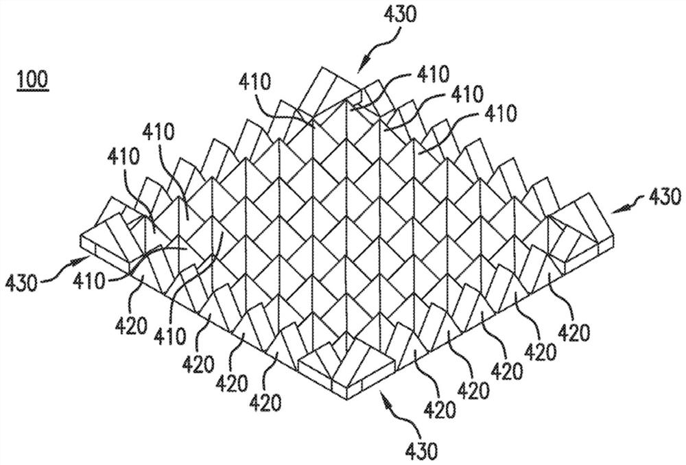
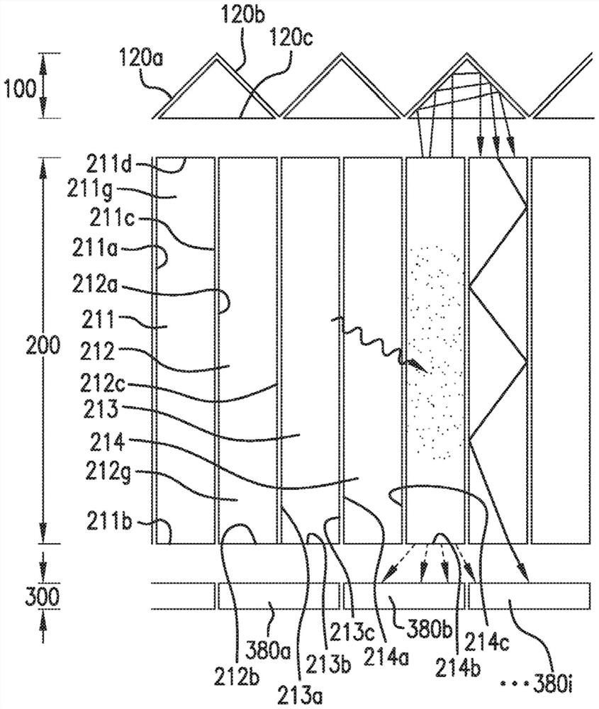
[0031] figure 1 is a quasi-cylindrical light guide according to an embodiment of the present invention. figure 1 The quasi-cylindrical light guide 100 is set on the scintillator array 200, and the scintillator array 200 is provided with a detector 300 on the opposite side of the quasi-cylindrical light guide 100. like figure 1 As shown, the pseudo-cylindrical light guide 100 includes a plurality of first pseudo-cylindrical bodies 410, the first pseudo-cylindrical bodies 410 may be triangular in shape, and the first pseudo-cylindrical bodies 410 are surrounded by second pseudo-cylindrical bodies 420 and angular pseudo-cylindrical bodies, See t...


PUM


Abstract

Provided are a device for detecting sub-atomic particles and a method of fabrication thereof. The device includes a plurality of scintillators, a detector provided on a first end of the plurality of scintillators and a prismatoid provided on a second end of the plurality of scintillators. The prismatoid redirects light between adjacent scintillators of the plurality of scintillators.

Description

[0001] priority [0002] This application claims the benefit of U.S. Provisional Application No. 62 / 789,559, filed January 8, 2019, with the USPTO and 62 / 957,991, filed January 7, 2020, the entire contents of which are hereby incorporated by reference into this article. [0003] governmental support [0004] This invention was made with government support under NIH grant number EB024849. The government has certain rights in this invention. technical field [0005] The present invention relates generally to the field of radiation imaging, and in particular to positron emission tomography (PET). Background technique [0006] PET is a nuclear medicine imaging technique that produces three-dimensional (3D) images to see processes in living tissue. PET is commonly used in clinical oncology to detect cancer and clinically to diagnose heart problems and / or brain disorders. Positron-emitting radionuclides introduced into organisms emit two photons in diametrically opposite dire...

Claims


Application Information

Patent Timeline
Patent Type & Authority Applications(China)
IPC IPC(8): G01T1/29A61B6/03G01T1/164
CPCA61B6/037G01T1/2002G01T1/2985G01T1/1642G01T1/1644
Inventor 阿米尔侯赛因·戈登安德鲁·拉贝拉赵伟安东尼·鲁宾斯基
Owner THE RES FOUND OF STATE UNIV OF NEW YORK
Why Eureka
Try Eureka