Direct current chiller method and system

A cooler, water-cooled technology, used in the storage of electric energy systems, parallel operation of DC power supplies, information technology support systems, etc.

Pending Publication Date: 2021-08-13
天加思茂特冷冻设备集团有限公司
View PDF0 Cites 0 Cited by
  • Summary
  • Abstract
  • Description
  • Claims
  • Application Information

AI Technical Summary

Problems solved by technology

These power converters are often developed to accommodate packaging constraints that may sacrifice efficiency and / or electrical noise for ease of integration into the motor itself

Method used


Image

  • Direct current chiller method and system
  • Direct current chiller method and system
  • Direct current chiller method and system

Examples


Embodiment Construction

[0015] The invention will be described in more detail by the following non-limiting examples.

[0016] Briefly, a cooler is provided comprising an oil-free magnetic swivel compressor that uses AC power and converts AC power to DC power so that it is a shaft suspension system, a compressor motor, and an airborne converter drive. (Vfd) provides power.

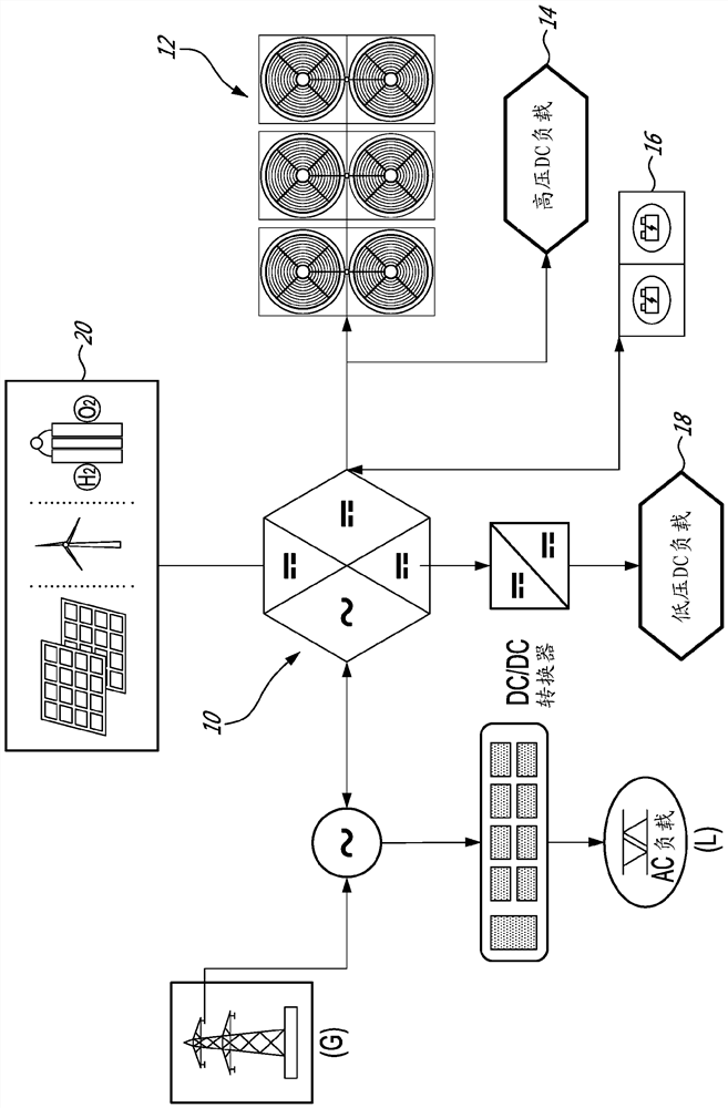
[0017] figure 2 A schematic diagram showing a system of a DC cooler and DC distributed power generation and an existing AC power distribution integrated in accordance with an aspect of the present invention are shown.

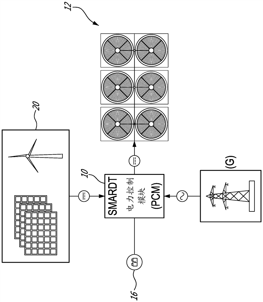
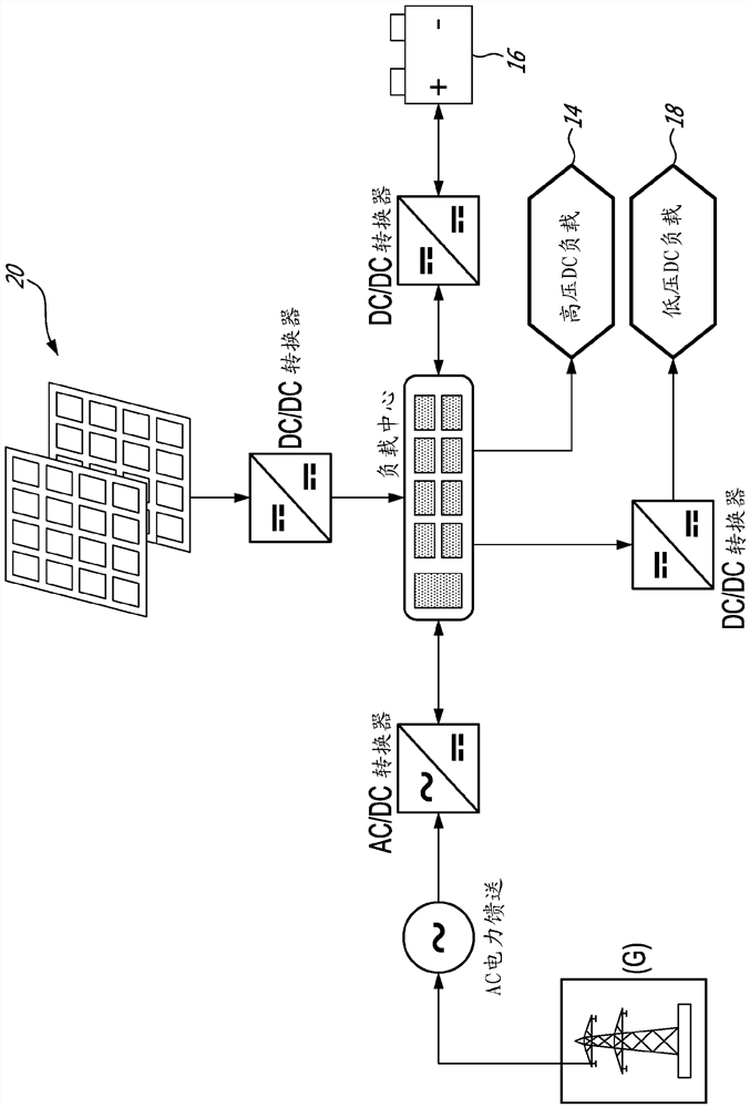
[0018] The power control module 10 connects the power grid (g) of the AC power delivered to the AC load (L) to DC loads 12, 14, 16, 18, and DC source 20. image 3 A power control module is shown in accordance with an embodiment of the present invention, which is designed to accommodate a plurality of different electrical energy / discharge points, such as solar panels, wind turbines, batteries, and grids.

[0019] The...


PUM


Abstract

A method and system for power supply integration, comprising interfacing at least one of : i) an AC power supply and ii) a DC power supply, and supplying, from the at least one of : i) an AC power supply and a ii) a DC power supply, DC power to the at least one DC load. The energy supply to the at least one DC load from the at least one AC power supply and the at least one DC power supply is controlled so as to selectively supply power from renewable energies for example.

Description

Technical field [0001] The present invention relates to a cooler method and a system. More specifically, the present invention relates to a method and system for a DC cooler. Background technique [0002] Heating, ventilation and air conditioning and cooling (HVACR) system consumes approximately 50% average buildings. As the cost of electricity has increased steadily, the building owners pay attention to its heating, ventilation and air conditioning system. In the United States, most of the power is transmitted through exchange (AC) delivery and power distribution (T & D) system, the T & D system is the old infrastructure of the transmission line. These old lines continue to reduce efficiency, which is a major role in the rise of electricity costs. These transport lines are not only old in terms of significant efficiency, but also the cost of upgrading T & D lines from $ 1 mm to $ 5 mm USD per mile. This dilemma is now forcing building owners to focus on efficiency improvement ar...

Claims


Application Information

Patent Timeline
Patent Type & Authority Applications(China)
IPC IPC(8): H02J1/00F24F13/00F25B1/00H02J1/12H02J15/00H02J3/38
CPCH02J3/38F25B27/00F24F11/88H02J2310/14H02J2300/20H02J7/35H02J3/32Y02E70/30Y04S20/222Y04S20/242Y02B70/30Y02B70/3225Y02P90/50Y04S20/244H02J5/00F25B30/02
Inventor V·卡尼诺G·图特维勒P·斯万S·约翰逊R·里士满-史密斯
Owner 天加思茂特冷冻设备集团有限公司
Why Eureka
Try Eureka