Renewable Energy Supply System, Island Operation Powerline and Method

a renewable energy and power supply technology, applied in the field of renewable energy supply systems, can solve the problems of low reliability of continuous power sources, use of fossil fuels, and the disadvantage of fluctuation gains of solar energy, so as to reduce the use of fossil fuels, and reduce the effect of fluctuation

Pending Publication Date: 2022-05-05
DANVEST ENERGY AS
View PDF5 Cites 0 Cited by
  • Summary
  • Abstract
  • Description
  • Claims
  • Application Information

AI Technical Summary

Benefits of technology

[0050]According to a further preferred embodiment, the Dump load control means control the Dump load to consume power generated by the solar energy and / or wind energy generator to down control the amount of solar energy and / or wind energy towards the main power line. This leads to the advantage that the dump load control can be used to offset variations in solar energy and / or wind energy this is particularly advantageous when excess solar energy and / or wind energy is available and fossil fuel usage is low or substantially 0. Also when the engine is assisting the renewable energy, it is advantageous that the load can take up more energy or stop taking up energy both ways in order to limit fluctuations both ways i.e. also limit the fluctuations that shall be handled by the engine. The voltage and the operating frequency of the main power line can be kept more stable.
[0051]A third mode of operation preferably comprises maintaining or enlarging a load on the Dump load based on renewable energy, allowing the internal combustion engine to increase rotational speed, such as including startup and / or raising fuel supply, while maintaining a balanced main power line by varying the Dump load while the internal combustion engine is increasing its rotational speed. This helps with starting up the engine or with allowing the engine to reach a higher power state from a relatively low power state. This has the advantage that the engine can regain driving power to the alternator helped by the Dump load control. The dump load level is low when the engine has lower capabilities and can take up more power as the alternative energy is still at high power and the engine is starting up such that the main power line remains substantially constant. It is highly advantageous that this can be performed while the engine keeps rotating at ratio's lower than 30% of the nominal power to even to minus 10-11% of nominal generator set power. It is provided that as the engine according to several preferred embodiments also operates under 30%, under 20%, under 10%, and even under 0% down to minus 10-11% of the nominal generator set power. Thus the engine can both save energy and return to energy supply levels of operation in seconds as it is kept warm and rotating, and / or it is highly efficiently assisted by the controls controlling the main power line during the engine startup and / or acceleration phase the present embodiment providing the engine with quicker response possibilities assisted via the pre pressuring and pre heating system. Furthermore, there is the possibility to remove i.e. relief dump when having to respond from reverse power operation with dump load controlling.

Problems solved by technology

Wind energy also has the well-known problem of being a fluctuating power source, and is therefore in itself unreliable as a continuous power source, at least unable to supply frequency and voltage and reactive power within desirable quality limits on its own.
Solar energy as well has that disadvantage of fluctuating gains.
The main disadvantage thereof is the use of fossil fuel and that CO2 is released into the atmosphere.

Method used


Image

  • Renewable Energy Supply System, Island Operation Powerline and Method
  • Renewable Energy Supply System, Island Operation Powerline and Method
  • Renewable Energy Supply System, Island Operation Powerline and Method

Examples


Embodiment Construction

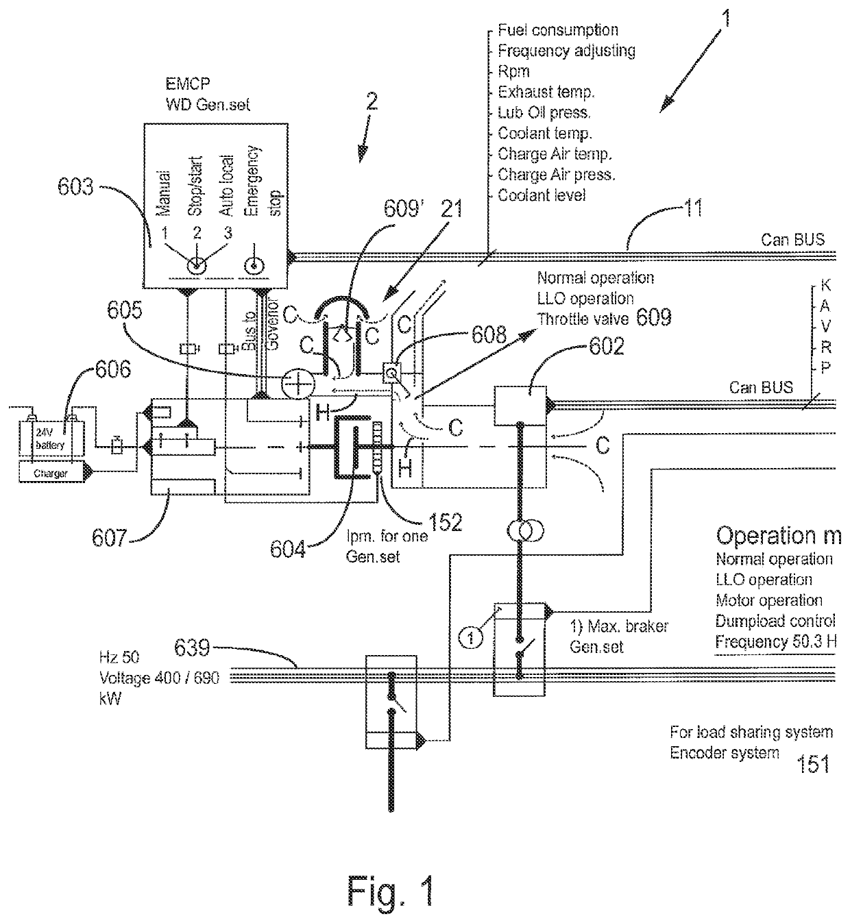
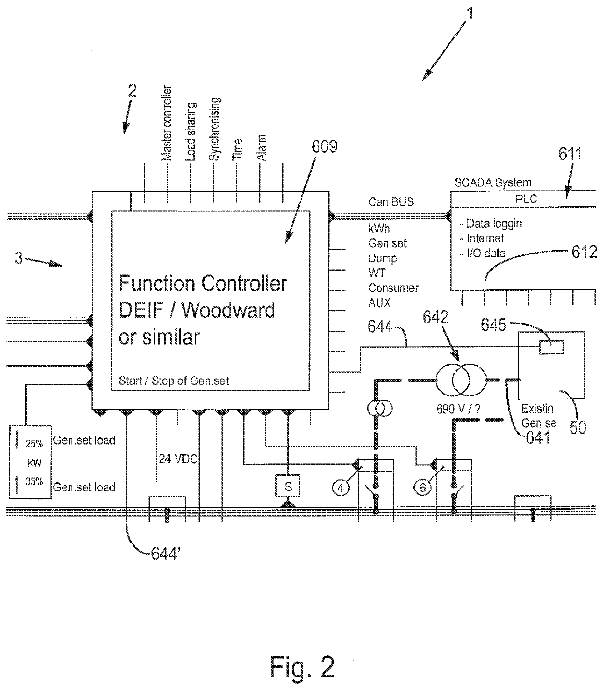
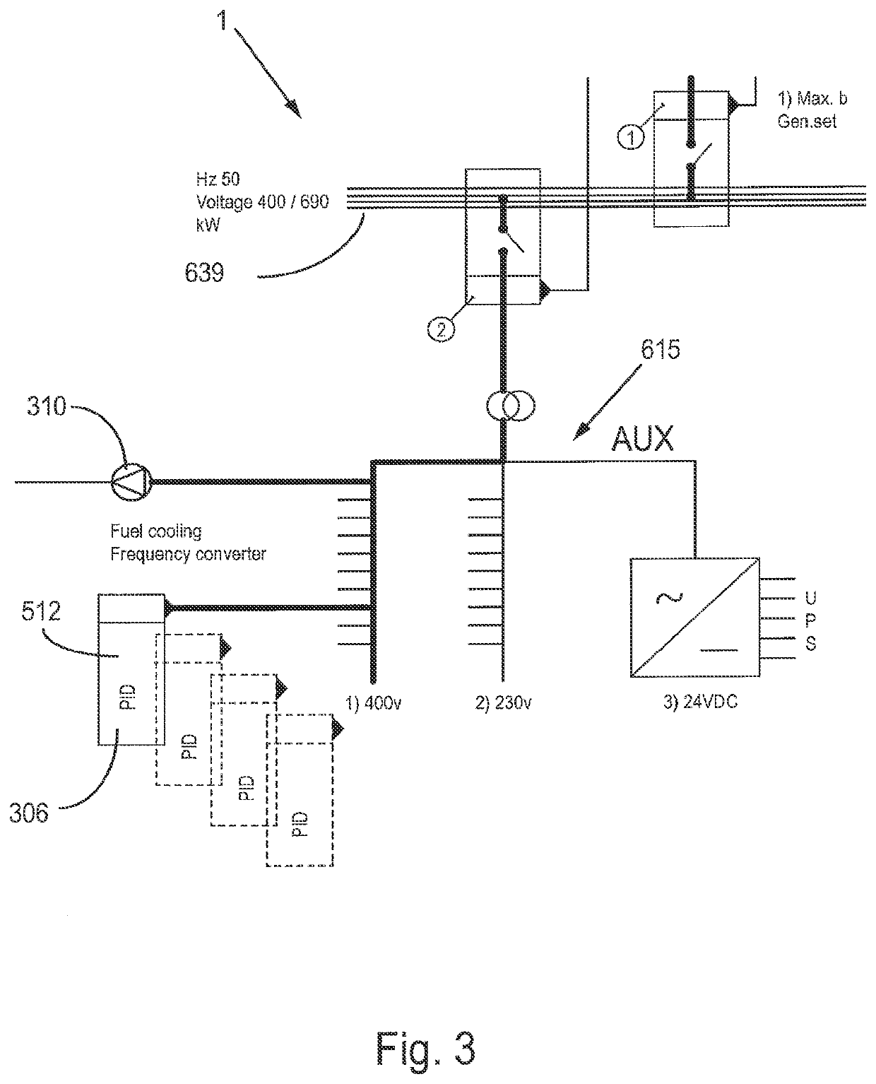
[0077]Provided in the FIGS. 1-4 is a system overview of a system 1 comprising features as included in preferred embodiments according to the present invention as indicated in the above. The system comprises a generator set 2, comprising generator set controlling means 609, a dump load system 614 for taking up excess energy comprising dump load system controlling means 613 (FIG. 4), as well as a cooling system station 615 comprising several subunits 306, preferably comprising a charge air cooler 512, for the generator set. Preferably, parts of the system are placed in a housing, such as one or more containers.

[0078]The generator set to is connected to a main power line 639. Also connected to the main power line is an alternative energy line 641 (FIG. 2) to supply electrical power from the alternative energy source 50, such as a wind generator 52 or a solar generator 51. The alternative energy source is coupled to the main power line 639 by means of transforming means 642. The represe...


PUM


Abstract

The invention is directed at a substantially continuous unbroken frequency curve during operation modes from dump load operation, reverse power operation, low load operation and normal operation. Controlling functions are active during all operation modes except the engine controller which is on standby when in an engine stopped mode. This all together gives a dynamic, robust and flexible energy supply, preferably in a range of 50 to 50.3 Hz. Further the clutching is performed substantially without fluctuations. The invention substantially prevents harmonic fluctuations to the grid. The main reactive power compensation is handled by the alternator always connected to the grid and rotating. Further reactive power compensation is done by a standard automatic reactive power compensation system. The invention contributes to stabilization of grid fluctuations with its mechanical inertia from the rotating alternator in the engine stopped mode and also with the engine in the other modes.

Description

CROSS-REFERENCE TO RELATED APPLICATIONS[0001]This application is a continuation of U.S. patent application Ser. No. 16 / 325,508, filed on Feb. 14, 2019, which is the United States national phase of International Application No. PCT / EP2017 / 070052 filed Aug. 8, 2017, and claims priority to Dutch Patent Application No. 2017316 filed Aug. 15, 2016, the disclosure of each of which is hereby incorporated by reference in its entirety.BACKGROUND OF THE INVENTIONField of the Invention[0002]The present invention relates to an energy supply system for providing electrical power from both a renewable energy source generated by a renewable energy generator, and a secondary energy source, such as fossil energy, generated by a generator set as backup for the renewable energy sources. Furthermore, the present invention relates to an island operation powerline. Furthermore, the present invention relates to a method for regulating an energy supply system according to the present invention. Fossil ener...

Claims


Application Information

Patent Timeline
Patent Type & Authority Applications(United States)
IPC IPC(8): H02J3/14G05F1/66
CPCH02J3/14Y04S20/222Y02B70/3225G05F1/66H02J2310/12H02J2300/10H02J2300/20H02J3/381Y02E10/56Y02E10/76H02J3/388H02J2300/28H02J2300/22
Inventor VESTESEN, SØREN QVIST
Owner DANVEST ENERGY AS
Why Eureka
Try Eureka