Magnetic recording apparatus and method of designing the same

a recording apparatus and magnetic recording technology, applied in special recording techniques, recording signal processing, instruments, etc., can solve the problems of physical limit of magnetic recording density, unreasonable to expect a further improvement of recording magnetic field, and inability to maintain the direction of spin once recorded, etc., to achieve easy to design, and the effect of high-density recording exceeding the thermal fluctuation limi

Inactive Publication Date: 2005-05-17
KK TOSHIBA
View PDF4 Cites 8 Cited by
  • Summary
  • Abstract
  • Description
  • Claims
  • Application Information

AI Technical Summary

Benefits of technology

[0009]An object of the present invention is to provide a magnetic recording apparatus capable of achieving a high-density recording exceeding the thermal fluctuation limit. Another object of the present invention is to provide a method that permits easily designing a magnetic recording apparatus capable of achieving a high-density recording exceeding the thermal fluctuation limit.

Problems solved by technology

However, there is a physical limit in the magnetic recording density.
However, if the magnetic particles are made very small, magnetic anisotropy energy, i.e., the product of magnetic anisotropy energy density Ku and magnetic particle volume, is rendered smaller than thermal fluctuation energy, with the result that it is impossible to maintain the direction of the spin once recorded.
It should be noted in this connection that the characteristics of a head magnetic pole material determining the recording magnetic field have substantially reached already a physical limit, making it unreasonable to expect a further improvement in the recording magnetic field.
In other words, it is impossible to comply with the demands for the increased recording density by simply increasing Ku.

Method used


Image

  • Magnetic recording apparatus and method of designing the same
  • Magnetic recording apparatus and method of designing the same
  • Magnetic recording apparatus and method of designing the same

Examples


example 1

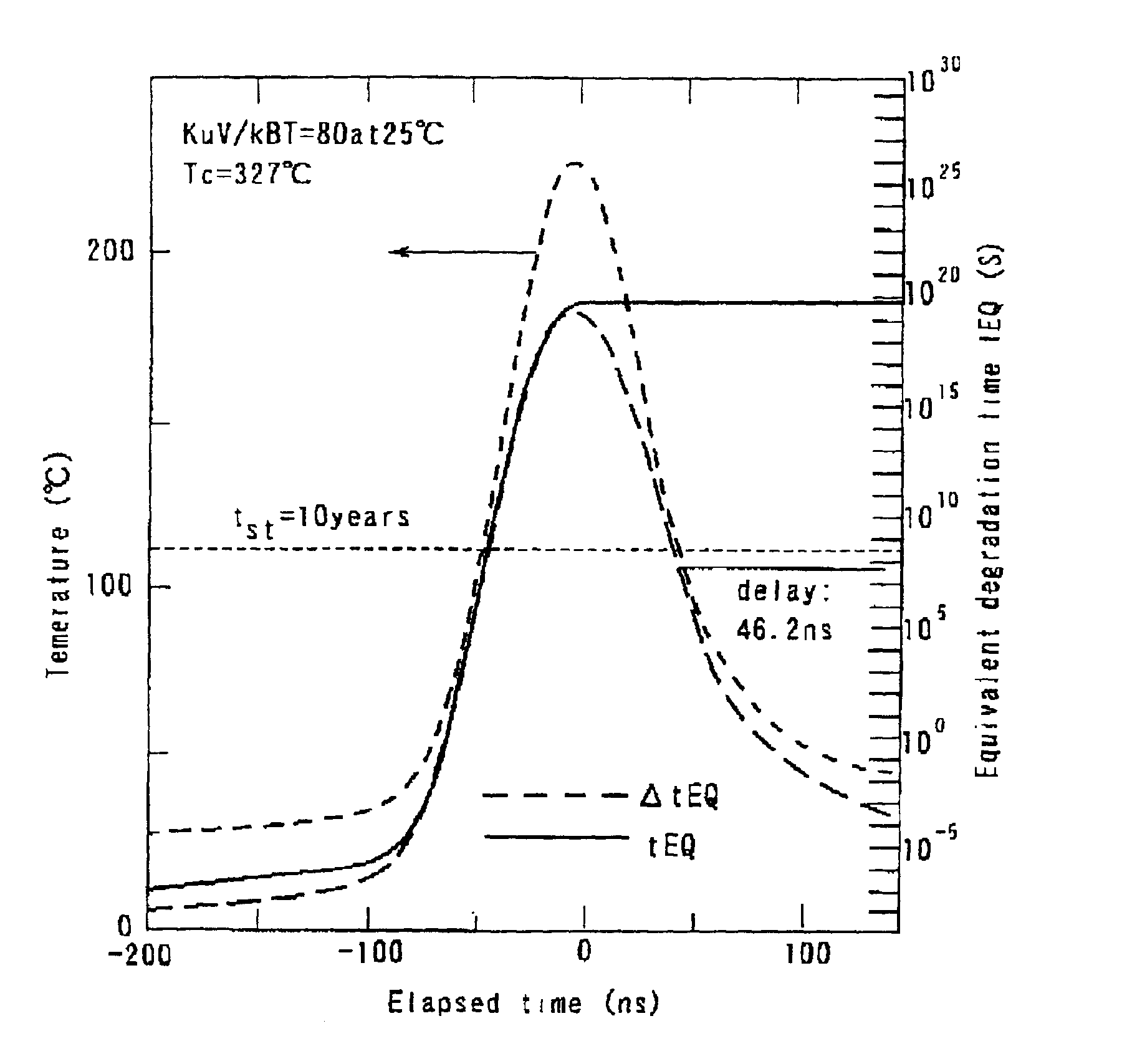
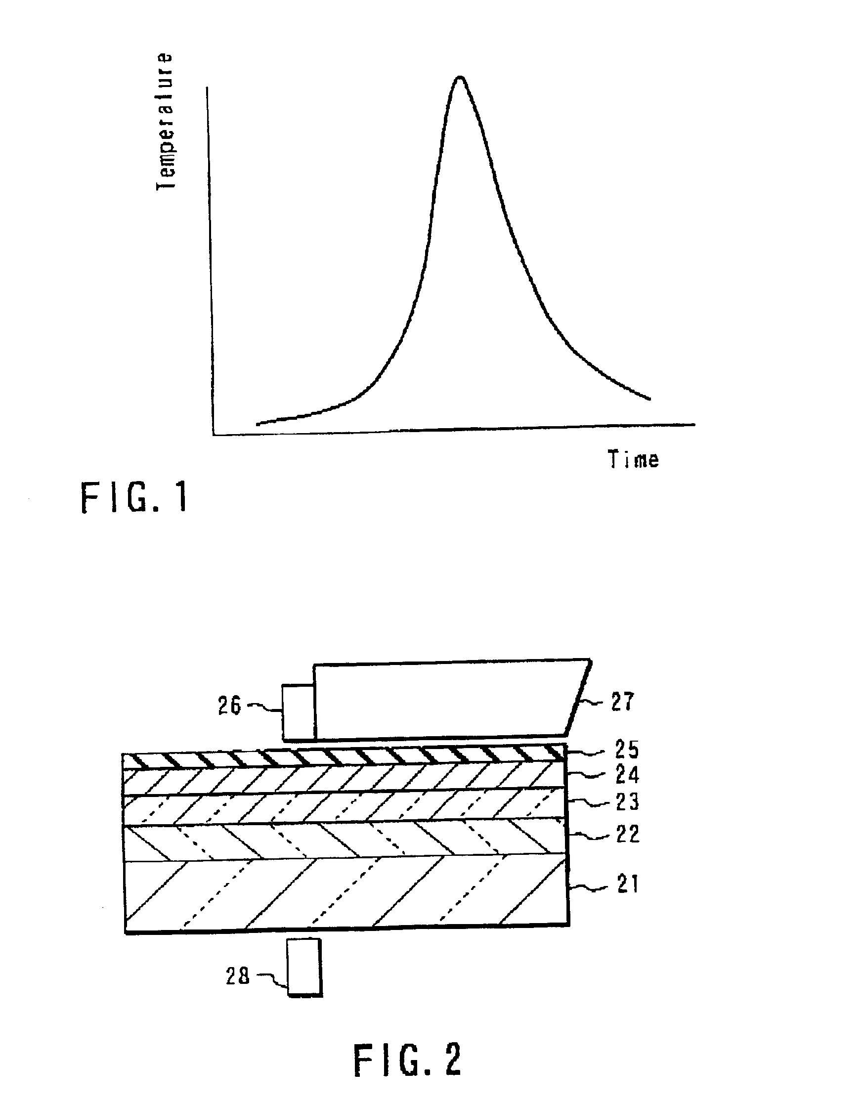
[0063]Fabricated was a magnetic recording apparatus constructed as shown in FIG. 2. The magnetic recording medium comprises a 2.5-inch glass substrate 21 and a stacked structure formed on the glass substrate 21, the stacked structure including the SiO2 first underlayer 22 having a thickness of about 100 nm, a ZnO second underlayer 23 having a thickness of about 140 nm, a CoCrPt magnetic recording layer 24 having a thickness of about 20 nm, and a carbon protective layer 25 having a thickness of about 10 nm. The slider 27 having a magnetic head equipped with the recording-reproducing element 26 mounted to the tip, which is similar to that used in the ordinary HDD apparatus, is arranged in the magnetic recording apparatus of the construction described above. When the magnetic recording medium is rotated, the slider 27 and the recording-reproducing element 26 are made in a floating state on the magnetic recording medium. In this magnetic recording apparatus, a flying height of 30 nm is ...

example 2

[0070]Fabricated was a magnetic recording apparatus equal to that prepared in Example 1, except that used was a magnetic recording layer differing in composition from that used in Example 1 and that the temperature of at which the coercive force Hc becomes substantially zero (Curie point Tc) was 500K (227° C.). For the magnetic recording layer, the value of βst of was 150. Also, the stable retention time tst required for the system was five years.

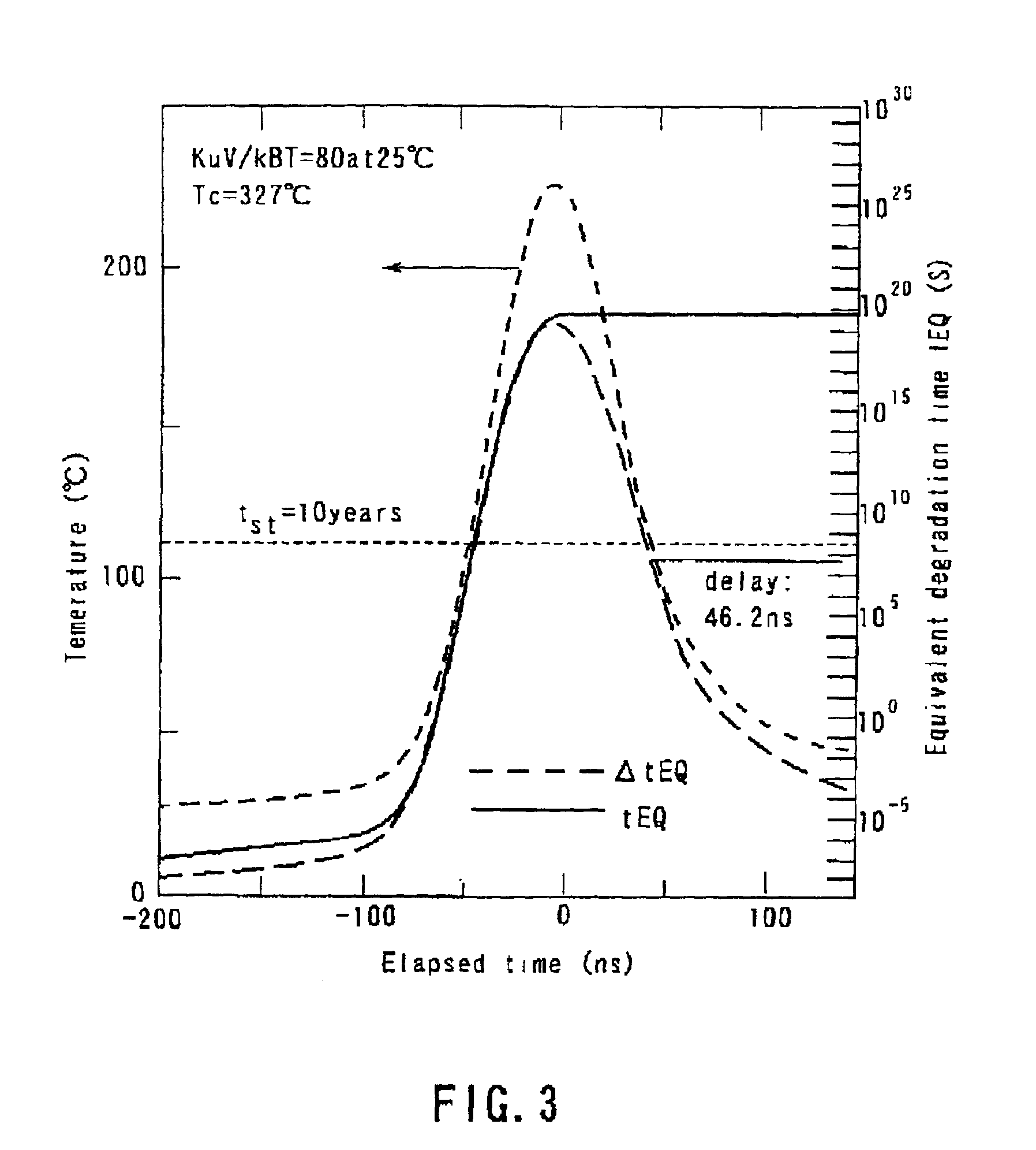
[0071]A recording experiment was conducted as in Example 1 in respect of the magnetic recording apparatus thus prepared. An analysis was performed as in FIG. 3, with the result that the magnetic field application time (delay) required for the recording was 54.6 ns. In fact, a high CNR was obtained when the distance between the recording gap and the laser spot was set at 300 nm, which corresponds to 60 ns, or more.

[0072]Another experiments were conducted, in which signals recorded with a single frequency by setting appropriately the distance...

example 3

[0076]Fabricated was a magnetic recording apparatus as in Example 1, except that the SiO2 underlayer was omitted to allow the underlayer to be formed of a ZnO layer alone having a thickness of about 100 nm and that the magnetic recording layer was formed of a CoPt—O layer having a thickness of about 20 nm. For the magnetic recording layer, the temperature at which the coercive force Hc becomes substantially zero (Curie point Tc) was 1420K, and the value of βst was 150. Also, the stable retention time tst required for the system was five years.

[0077]Experiments were conducted in respect of the magnetic recording apparatus, in which the magnetic recording medium was irradiated with a laser beam after the thermally-assisted magnetic recording as in Example 2. In Example 3, however, in order to examine the resistance to cross erase, the irradiating portion with the laser beam was displaced from the initial recording track at an interval of 10 nm and brought back again to the portion of ...


PUM

PropertyMeasurementUnit
retention time tstaaaaaaaaaa
timeaaaaaaaaaa
timeaaaaaaaaaa

Abstract

A method of designing a thermally-assisted magnetic recording apparatus having a magnetic recording medium, a heater and a magnetic head includes, determining a stable retention time tst for recorded magnetization and a thermal-fluctuation stability coefficient βst calculated from β(T)=KuV/kBT, where Ku is a magnetic anisotropy energy density, V is an activation volume, and kB is Boltzmann's constant, obtaining an equivalent degradation time tEQ calculated from tEQ=Σ(ΔtEQ), that sums values of ΔtEQ within a period of time Δt for a time span during which the medium is substantially degraded, where ΔtEQ=exp(ln(Δt)−β−βst) and β is a thermal-fluctuation stability coefficient for a medium temperature T in Δt, and determining specifications of the medium, the heater and the magnetic head in a manner to meet the relationship of tEQ<tst.

Description

CROSS-REFERENCE TO RELATED APPLICATIONS[0001]This application is based upon and claims the benefit of priority front the prior Japanese Patent Application Ser. No. 2000-296835, filed Sep. 28, 2000, the entire contents of which are incorporated herein by reference.BACKGROUND OF THE INVENTION[0002]1. Field of the Invention[0003]The present invention relates to a magnetic recording apparatus and a method of designing the same.[0004]2. Description of the Related Art[0005]With improvement in the processing speed of computers achieved in recent years, high-density recording has been required for magnetic recording apparatuses (HDD) for recording and reproducing information. However, there is a physical limit in the magnetic recording density.[0006]In order to achieve high-density magnetic recording, it is necessary to reduce the size of magnetic domains recorded in the magnetic recording layer. For distinguishing each recorded small magnetic domain clearly, it is necessary for the domain ...

Claims


Application Information

Patent Timeline
Patent Type & Authority Patents(United States)
IPC IPC(8): G11B5/00G11B5/62G11B33/14
CPCG11B5/00G11B5/62G11B2005/0021G11B2005/0002G11B2005/0005G11B33/14
Inventor KIKITSU, AKIRAAKIYAMA, JUNICHI
Owner KK TOSHIBA
Why Eureka
Try Eureka