
Magnetic disk drive

a magnetic disk and drive technology, applied in mechanical recording, nanoinformatics, instruments, etc., can solve the problems of large difference between recording head and reproducing head, inability to increase the area recording density, and predicted thermal fluctuation resistance limi

Inactive Publication Date: 2008-07-31
WESTERN DIGITAL TECH INC
View PDF11 Cites 8 Cited by
  • Summary
  • Abstract
  • Description
  • Claims
  • Application Information

AI Technical Summary

Benefits of technology

[0003]As a solution to this problem, a perpendicular recording method has been developed. The perpendicular recording method records magnetic signals on a double-layered perpendicular medium having a soft-magnetic underlayer with a single-pole head perpendicularly. This method can apply a stronger recording magnetic field to the medium. Therefore, a recording layer of a medium with a large magnetic anisotropy constant (Ku) can be used. Besides, in a magnetic recording medium in the perpendicular magnetic recording method, an advantage of increasing V while keeping the magnetic particle diameter on the medium surface small, or keeping the bit length small has been achieved by growing magnetic particles in the film thickness direction. However, a limit to the thermal fluctuation resistance is predicted even in the perpendicular magnetic recording method if higher-density magnetic recording media are realized in the future.

Problems solved by technology

However, decreasing a recording bit length causes a problem that the area recording density cannot be increased due to thermal fluctuation in magnetization of the medium.
However, a limit to the thermal fluctuation resistance is predicted even in the perpendicular magnetic recording method if higher-density magnetic recording media are realized in the future.
Since the head structure shown in FIG. 12 includes the auxiliary pole 3 and the thin film coil 2 between the reproducing element 7 and the main pole 1, the distance between the recording head and the reproducing head becomes large so that format efficiency is disadvantageously deteriorated.

Method used


Image

  • Magnetic disk drive
  • Magnetic disk drive
  • Magnetic disk drive

Examples


Embodiment Construction

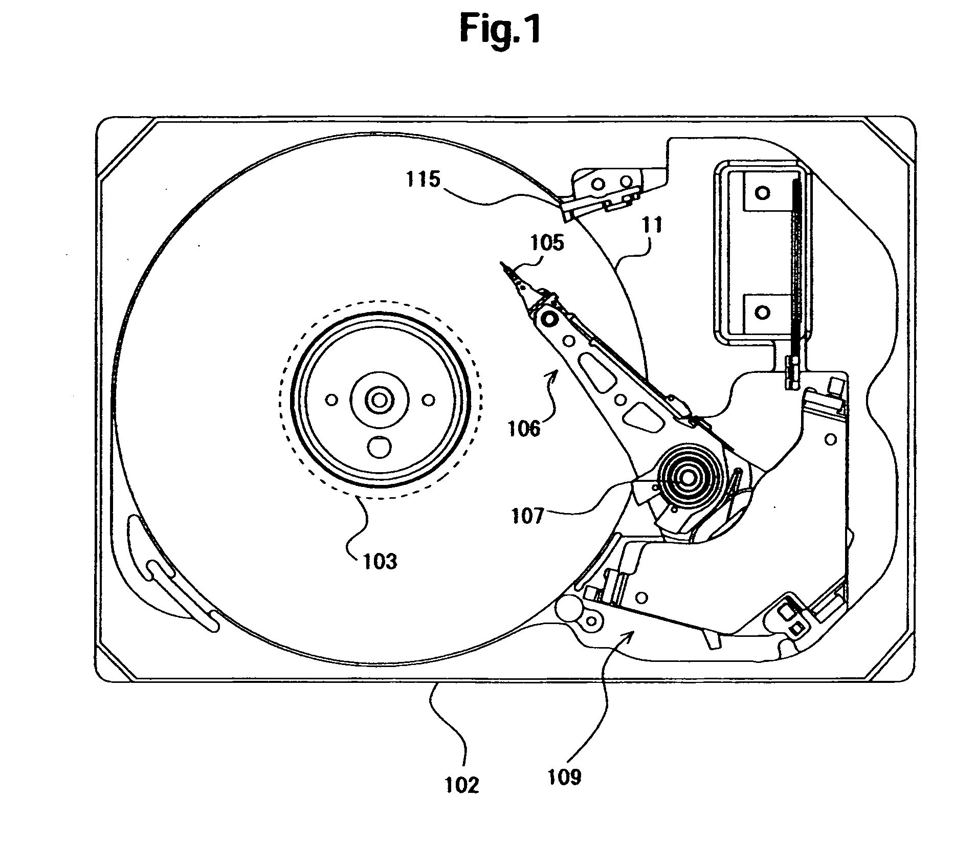
[0031]Embodiments of the present invention relate to a magnetic disk drive, particularly to a magnetic disk drive equipped with a magnetic head having side shields for perpendicular magnetic recording and a magnetic disk having a concavo-convex structure for defining a track width.

[0032]It is an object of embodiments of the present invention to solve the problem that the data on the adjacent tracks are attenuated or deleted by the leaked recording field from the main pole to the adjacent track excited by the recording current running through the coil in the recording head.

[0033]A magnetic disk device according to an aspect of embodiments of the present invention comprises a magnetic disk for perpendicular magnetic recording and a magnetic head for perpendicular magnetic recording. The magnetic disk has a magnetic recording layer and an underlayer under the magnetic recording layer, and further including a groove and a land for defining a track width on at least one of the magnetic r...


PUM


Abstract

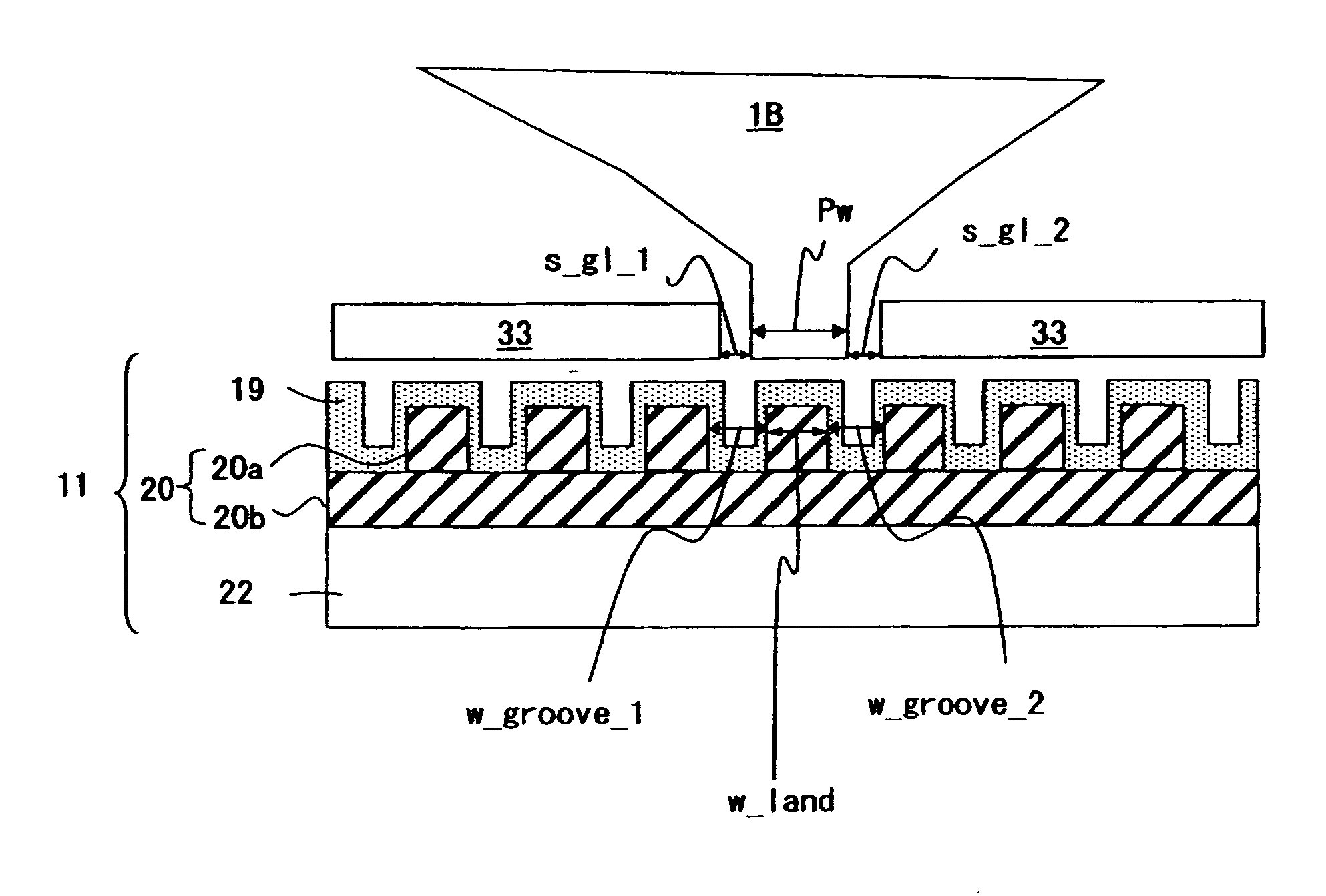
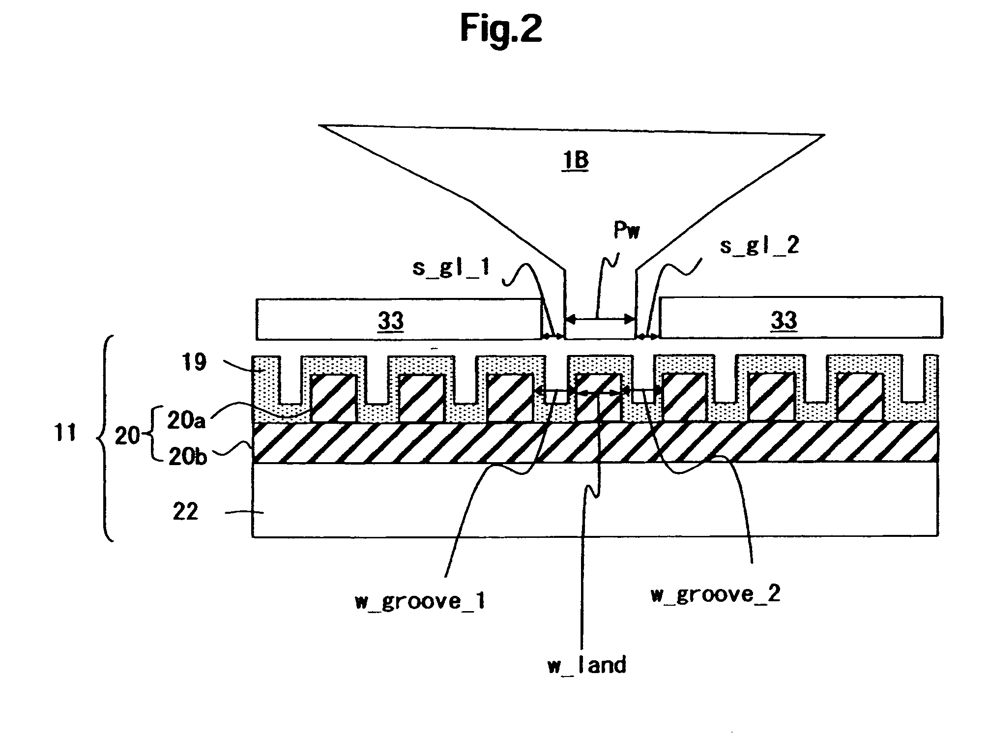
In a patterned perpendicular magnetic recording medium, embodiments of the present invention provide a magnetic head in which magnetic field to be applied to adjacent tracks can be suppressed and a recording device equipped with the magnetic head. In one embodiment of the present invention, a sum of a width Pw of a main pole of a magnetic head and distances between right and left magnetic substances on a width-directional side of tracks and the main pole, so-called widths of side gap lengths s_g1—1 and s_g1—2 is, in a magnetic recording medium having a soft-magnetic underlayer, made to be not more than a sum of a width w_land of a convexity or land of the soft-magnetic underlayer and widths w_groove—1 and w_groove—2 of concavities or grooves adjacent to the land on both its sides.

Description

CROSS-REFERENCE TO RELATED APPLICATION[0001]The instant nonprovisional patent application claims priority to Japanese Patent Application No. 2007-009094 filed Jan. 9, 2007 and which is incorporated by reference in its entirety herein for all purposes.BACKGROUND OF THE INVENTION[0002]A magnetic recording and reproducing device comprises a magnetic recording medium and a magnetic head, and data on the magnetic recording medium is read and written by means of the magnetic head. In order to increase recording capacity per unit area on the magnetic recording medium, it is required to increase area recording density. However, decreasing a recording bit length causes a problem that the area recording density cannot be increased due to thermal fluctuation in magnetization of the medium. Generally, influence by the thermal fluctuation will increase as the value of Ku·V / kT is smaller, where Ku, V, k, and T represent a magnetic anisotropy constant, a minimum unit volume for magnetization, a Bo...

Claims


Application Information

Patent Timeline
IPC IPC(8): G11B5/127
CPCB82Y10/00G11B5/855G11B5/743G11B5/1278
Inventor MOCHIZUKI, MASAFUMISHIMIZU, YUKIYANISHIDA, SHUJI
Owner WESTERN DIGITAL TECH INC
Learn More