Laser spark plug for an internal combustion engine

a technology for internal combustion engines and spark plugs, which is applied in the direction of engine ignition, electrical equipment, electric ignition installation, etc., can solve the problems of reducing the service life of spark plugs, affecting the efficiency of combustion engines, so as to achieve better sealing action, promote heat dissipation, and increase the effect of heat dissipation

Inactive Publication Date: 2014-09-09
GE JENBACHER
View PDF21 Cites 5 Cited by
  • Summary
  • Abstract
  • Description
  • Claims
  • Application Information

AI Technical Summary

Benefits of technology

[0007]Therefore, the object of the present invention is to provide devices of the kind set forth in the opening part of this specification, in which those disadvantages are reduced, that is to say in which there are no temperature problems in the region of the laser light producing device, generally a laser crystal.
[0021]All the stated features essentially serve to provide that the heat input surface from the combustion chamber is relatively small because of the small end diameter, at the combustion chamber side, of the laser spark plug, and a large part of the heat transmitted to the laser spark plug is dissipated into the preferably water-cooled cylinder head wall. Optionally provided heat-dissipating, preferably areal sealing elements and heat-conducting sealing elements which are arranged at a very small spacing relative to the end towards the combustion chamber of the laser spark plug for example in the form of a support ring between the screw-in portion (for example hexagonal shoulder) and fixing region or cylinder head wall, also involving a large surface area, promote the dissipation of heat into the cylinder wall.
[0022]It is thus possible to ensure that the heat is dissipated over a very wide and long laser spark plug region into the cylinder head wall. With decreasing temperature of the cylinder wall at an increasing distance relative to the combustion chamber surface, the temperature of the spark plug housing decreases in the same way as the cylinder wall, and has only a slight excess in relation to the engine cooling water temperature at the location of the contact surface.

Problems solved by technology

One of those advantages is the absence of erosive wear and hot corrosion at the spark plug electrodes, which in conventional electric spark ignition, specifically in relation to the high power density levels of modern gas engines, lead to reduced spark plug service lives and thus considerable operating costs.
In large high-power gas engines, the components delimiting the combustion chamber are subjected to very high thermal loading.
That can be achieved only with difficulty with the geometrical configurations known at the present time of the laser spark plugs, under unfavorable boundary conditions.

Method used


Image

  • Laser spark plug for an internal combustion engine
  • Laser spark plug for an internal combustion engine
  • Laser spark plug for an internal combustion engine

Examples


Embodiment Construction

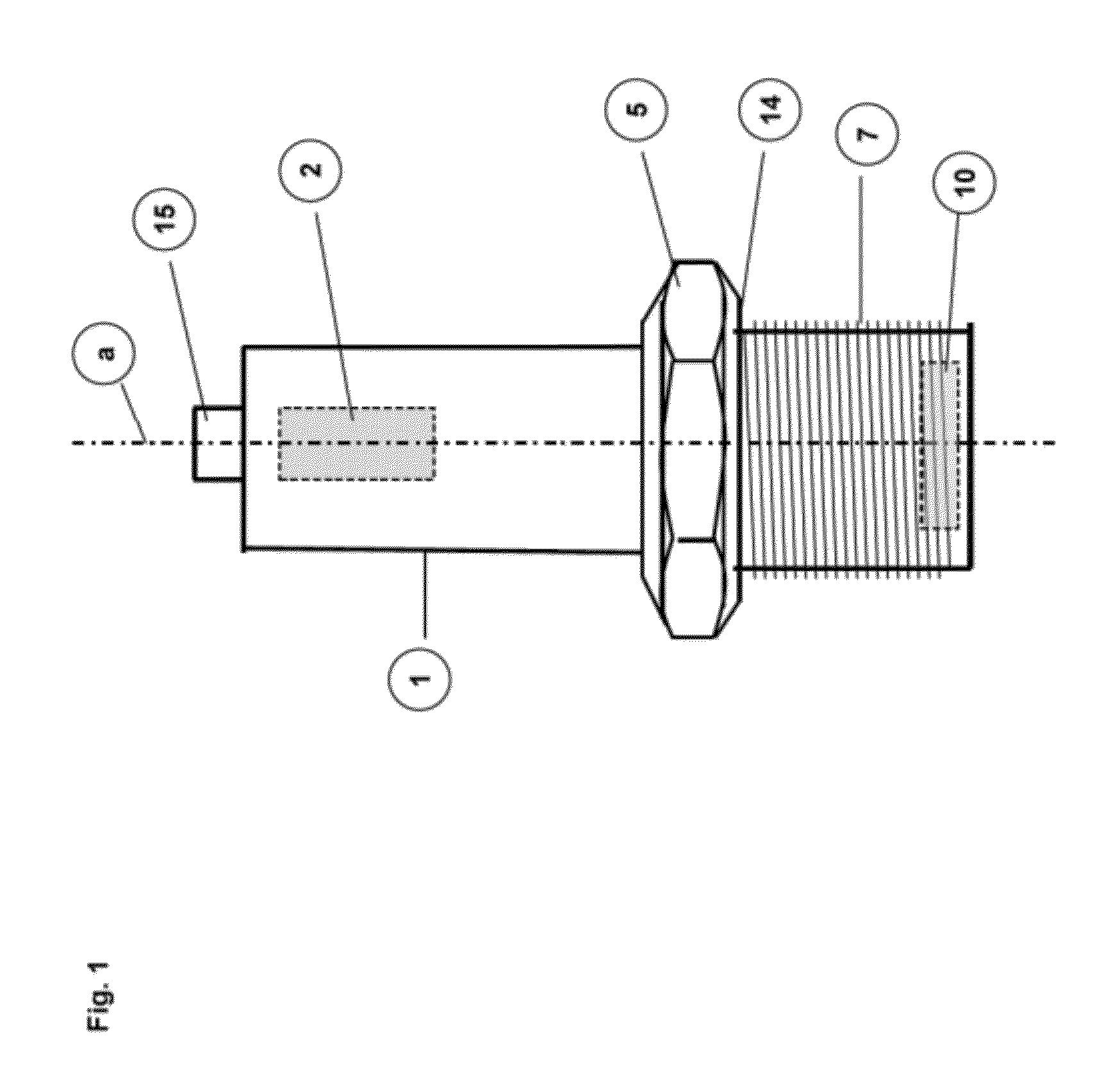
[0032]FIG. 1 diagrammatically shows a laser spark plug in accordance with the state of the art. It includes a spark plug housing 1 extending along the longitudinal axis of the laser spark plug a. The coupling-in optical member 10—also referred to as the combustion chamber window—is arranged at an end, (more specifically the end towards the combustion chamber) of the laser spark plug. The coupling-in optical member 10 is responsible for coupling the laser light produced by a laser light producing device 2 into the combustion chamber of the internal combustion engine. The laser light producing device 2 in this case is in the form of a monolithic solid-state laser (laser crystal) and is fed by a pump light source (not shown). Disposed at the connection (upper) end of the laser spark plug is a connection portion 15 for introducing the pump light.

[0033]Disposed at the end of the laser spark plug, towards the combustion chamber, is a fastening region 7 in the form of a male screwthread 7 ...


PUM


Abstract

A laser spark plug includes a laser light-producing device and a spark plug housing at the end of which facing the combustion chamber an injection lens for injecting laser light into the combustion chamber of an internal combustion engine is arranged. The spark plug housing includes a fastening zone for fastening the laser spark plug in a cylinder head of the internal combustion engine. A projection on the end of the spark plug housing facing the combustion chamber houses the injection lens. The outer diameter (D1) of the projection is smaller in the area of the injection lens than the outer diameter (D2) of the spark plug housing in the fastening zone.

Description

[0001]This application is a Continuation of International application No. PCT / AT2010 / 000351, filed Sep. 27, 2010, the entire disclosure of which is incorporated herein by reference.BACKGROUND OF THE INVENTION[0002]The invention concerns a laser spark plug comprising a laser light producing device and a spark plug housing, at whose end towards the combustion chamber there is arranged a coupling-in optical means for coupling laser light into the combustion chamber of an internal combustion engine. The spark plug housing has a fastening region for fastening the laser spark plug in a cylinder head of the internal combustion engine.[0003]The invention further concerns an arrangement including a laser spark plug of the aforementioned kind and a cylinder head having a fixing region for the fastening region of the laser spark plug. Finally, the invention concerns an internal combustion engine, in particular a gas engine, comprising such an arrangement.[0004]Laser ignition is an ignition sys...

Claims


Application Information

Patent Timeline
Patent Type & Authority Patents(United States)
IPC IPC(8): F02B23/00F02P23/04
CPCF02P23/04
Inventor GRUBER, FRIEDRICHKRAUS, MARKUS
Owner GE JENBACHER
Why Eureka
Try Eureka