Portable watch

a technology of portability and watch, applied in the field of portability watches, can solve the problems of excessive operation force, difficult to know the winding state of the spiral spring in the case band, and inability to know the winding state of the screw lock operation, etc., and achieve the effect of not being turned carelessly

Active Publication Date: 2005-04-28
SEIKO INSTR INC
View PDF8 Cites 9 Cited by
  • Summary
  • Abstract
  • Description
  • Claims
  • Application Information

AI Technical Summary

Benefits of technology

[0014] In order to solve the problem, the present invention is a portable watch in which a crown is held so as not to be turned carelessly utilizing engagement of screws, the crown including: a crown shaft that moves a winding stem in association with the crown shaft; a crown head that has a female screw section to be detachably engaged with a male screw section of a pipe attached to a case ...

Problems solved by technology

However, it is impossible to know in which winding state the spiral spring in the case band is.
In this case, the screw lock operation becomes particularly heavy, which is inconvenient.
Accordingly, an excessive operation force is applied to the male scre...

Method used


Image

  • Portable watch
  • Portable watch
  • Portable watch

Examples


first embodiment

[0030] (First Embodiment)

[0031] A first embodiment of the present invention will be explained with reference to FIGS. 1 to 5.

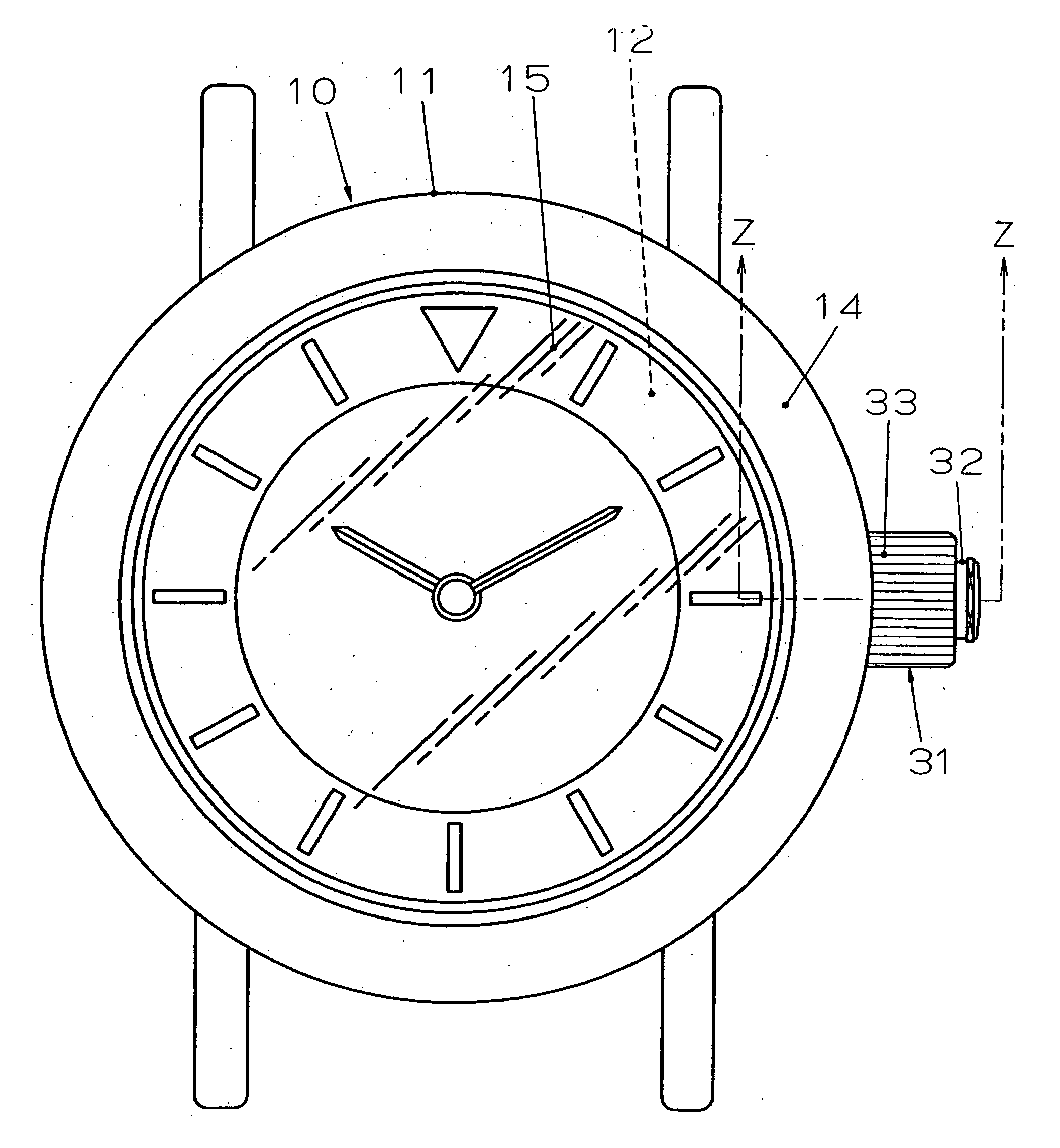
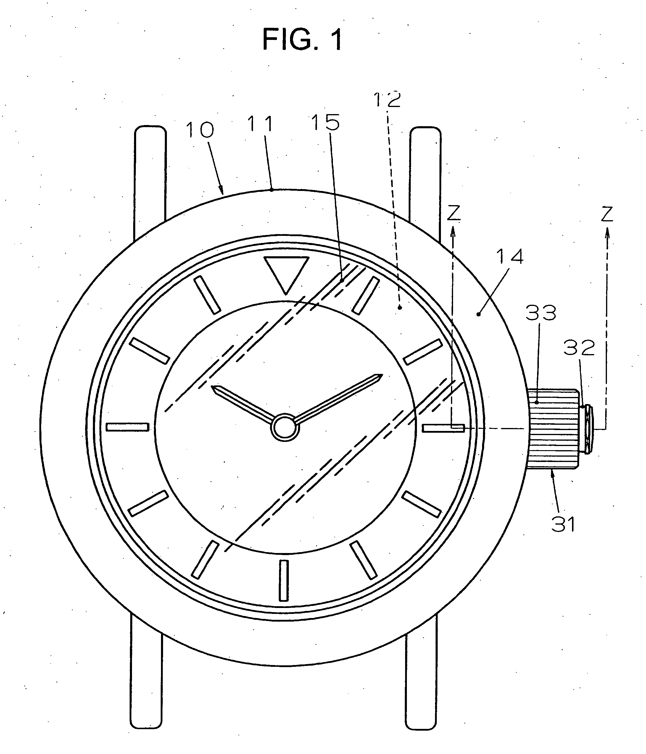
[0032] In FIG. 1, reference numeral 10 denotes a wristwatch as a portable watch. As shown in FIGS. 2 and 3, this wristwatch 10, houses a dial 12, a not-shown watch movement 13, and the like in a watch exterior assembly 11. As the watch movement 13, a mechanical watch movement of a manual winding type with a spring as a drive source, an automatic winding type, or a type using both manual winding and automatic winding is used. Note that, instead of these types, a watch movement of a type, which can select and switch digital display and analog display as time display or the like on the dial 12, may be adopted.

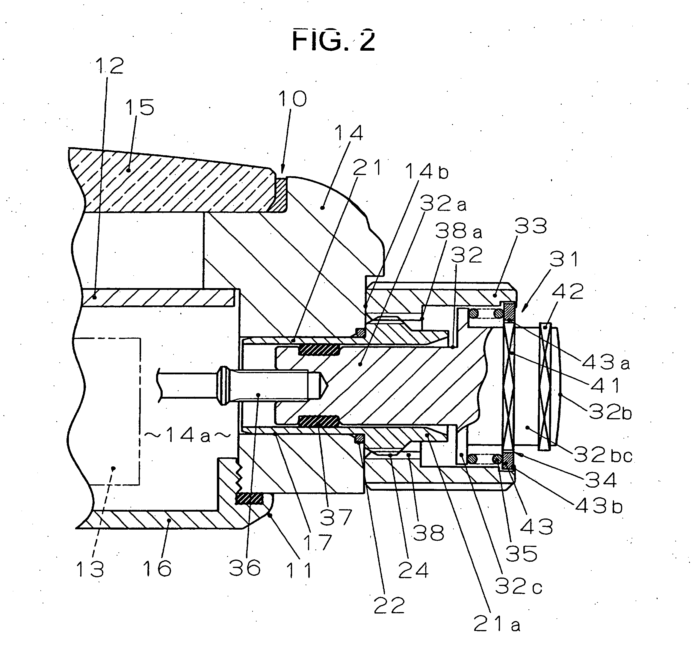
[0033] As shown in FIGS. 2 and 3, the watch exterior assembly 11 is formed by mounting a cover glass 15 liquid-tightly on a front surface, which consists of one surface in a thickness direction, of an annular metal case band 14, and screwing a case back 16...

second embodiment

[0057] (Second Embodiment)

[0058] A second embodiment of the present invention will be explained with reference to FIG. 6 showing the screw lock state of the crown 31 and FIG. 7 showing a state in which the screw lock state of the crown 31 is released. Since this second embodiment is basically the same as the first embodiment, components same as those in the first embodiment are denoted by reference numerals and signs identical with those in the first embodiment, and an explanation about the components will be omitted. Components different from those in the first embodiment will be explained.

[0059] In the second embodiment, the female screw section 38, which is provided separately from the crown head 33, fixed to the inner periphery at one end in the axial direction of the crown head 33 by caulking. Moreover, the driving section 43 of the clutch 34 is formed integrally with the inner periphery at the other end in the axial direction of the crown head 33. Other than the points explai...


PUM


Abstract

To provide a portable watch in which a crown can be held so as not to be turned carelessly utilizing engagement of screws without being restricted by a function of a watch movement, durability is improved, and a screw lock operation for the crown is light. The present invention is premised on a portable watch in which a crown, which is connected to a winding stem transmitting a turning force to a watch movement in a case band, is engaged with a male screw section of a pipe attached to the case band, whereby a crown is held so as not to be turned. The crown includes: a crown shaft that moves the winding stem in association with the crown shaft; a crown head that turns the crown shaft in a state in which the engagement is released; and clutch. The crown head has a female screw section that is detachably engaged with the male screw section. The clutch couples the crown shaft and the crown head so as to prevent the turn of the crown shaft in a state in which the engagement is completed, and couples the crown shaft and the crown head so as to make it possible to turn the crown shaft following the crown head in a state in which the engagement is released.

Description

BACKGROUND OF THE INVENTION [0001] 1. Field of the Invention [0002] The present invention relates to a portable watch in which a crown is held so as not to be turned carelessly utilizing engagement of screws. [0003] 2. Description of the Prior Art [0004] Conventionally, a crown for operating a watch movement incorporated in a case band is a single component and includes a crown shaft section that moves the watch movement in association with the crown shaft section and a crown head that is formed integrally with this shaft section. The crown shaft section is inserted in a winding stem pipe, which is attached to the case band, and the crown head is fitted into a pipe end, which is located outside the case band, of the winding stem pipe. [0005] There is known a portable watch in which, in order to prevent this crown from being turned carelessly, a male screw section is formed on an outer periphery of the pipe end, which is located outside the case band, of the winding stem pipe, and a ...

Claims


Application Information

Patent Timeline
IPC IPC(8): G04B37/10
CPCG04B37/103
Inventor HIRANUMA, HARUKIOOMORI, NOBUKAZU
Owner SEIKO INSTR INC
Why Eureka
Try Eureka