
Portable watch

a technology of timepieces and straps, applied in the field of portable timepieces, can solve the problems of excessive operation force, difficult to know the winding state of the spiral spring in the case band, and the operation of screw locks is particularly heavy, so as to avoid being turned carelessly

Active Publication Date: 2007-03-20
SEIKO INSTR INC
View PDF9 Cites 11 Cited by
  • Summary
  • Abstract
  • Description
  • Claims
  • Application Information

AI Technical Summary

Benefits of technology

The present invention is a portable timepiece with a unique clutch mechanism that prevents the crown from turning when not in use. The clutch includes a driving section and a receiving section that are engaged when the crown is turned. The clutch is designed to release the engagement when the crown is turned in the opposite direction, allowing the crown to move and engage with the case band. The clutch is simple in structure and can be easily controlled to prevent unwanted movement of the crown. The invention also includes a screw lock mechanism that allows for secure operation of the watch movement without transmitting any movement to the crown.

Problems solved by technology

It is undesirable to apply the technique of the JP-A-57-46181 to a portable watch, which has a function of winding up a spiral spring with a crown arranged in a “zero stage”, or a portable watch, which has a function of changing an operation mode, due to the following reasons.
However, it is impossible to know in which winding state the spiral spring in the case band is.
In this case, the screw lock operation becomes particularly heavy, which is inconvenient.
Accordingly, an excessive operation force is applied to the male screw section and the female screw section, and abrasion of these screw sections is accelerated.
Consequently, the technique, which utilizes engagement of screws to prevent a crown from being turned carelessly, cannot be applied to the portable watch of this type.

Method used


Image

  • Portable watch
  • Portable watch
  • Portable watch

Examples


first embodiment

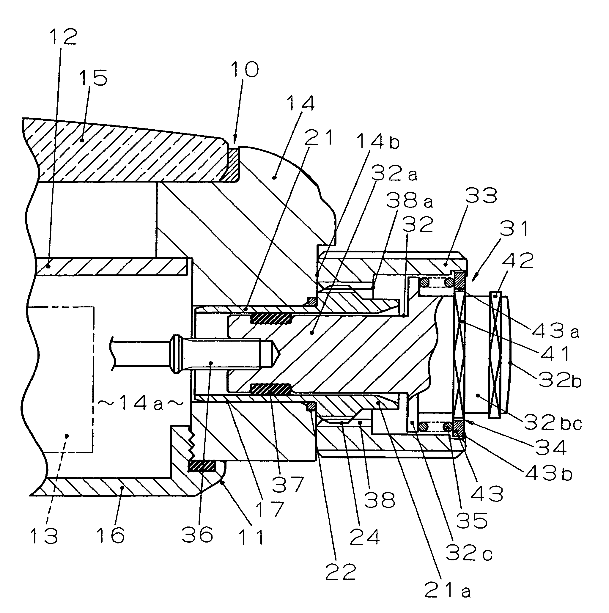
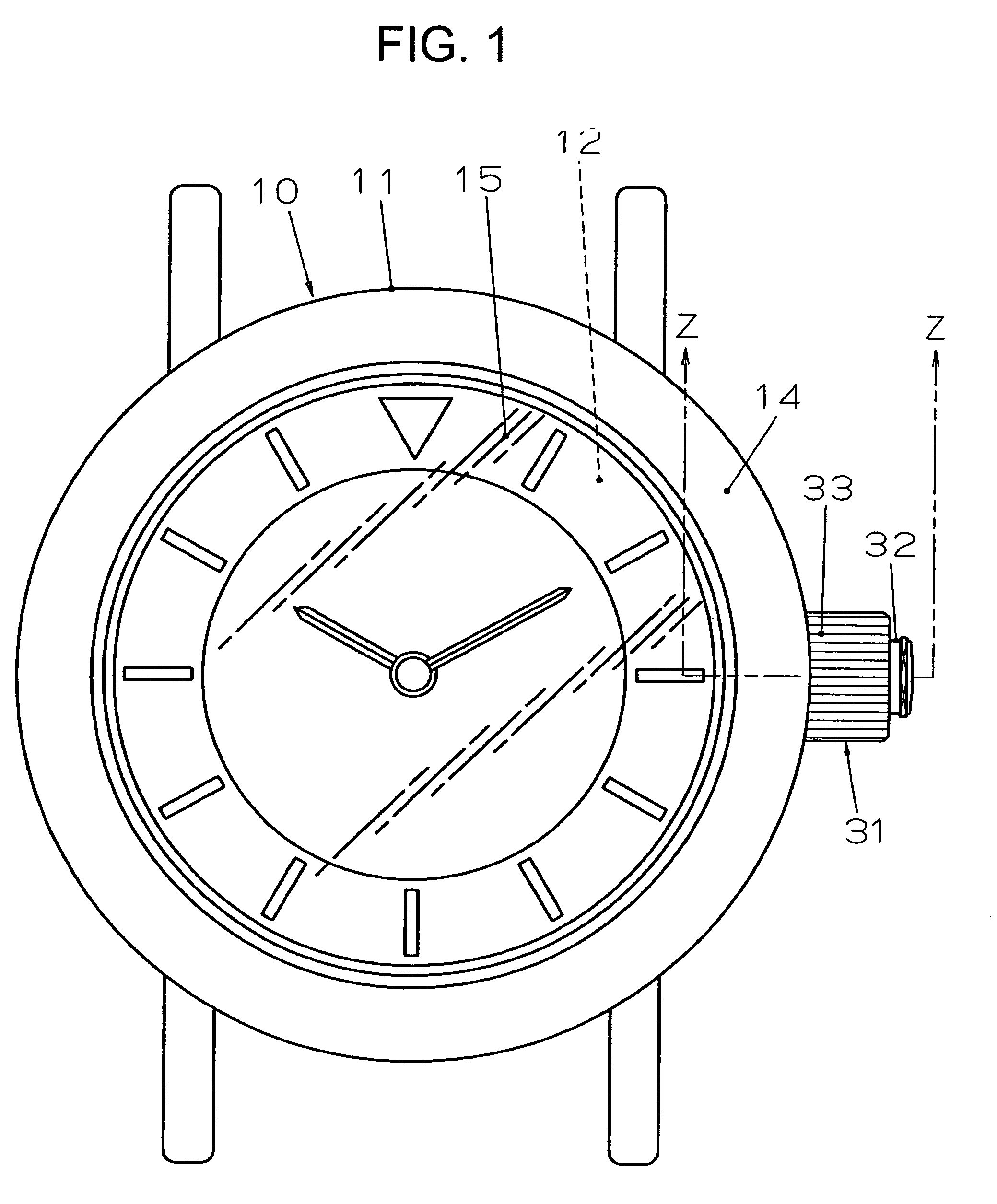
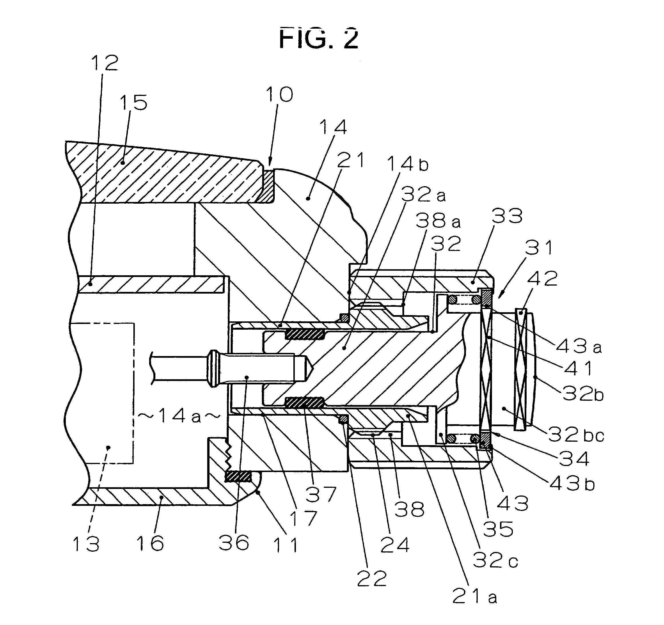
[0030]A first embodiment of the present invention will be explained with reference to FIGS. 1 to 5.

[0031]In FIG. 1, reference numeral 10 denotes a wristwatch as a portable clutch. As shown in FIGS. 2 and 3, this wristwatch 10 houses a dial 12, a watch movement 13, and the like in a case or watch exterior assembly 11. As the watch movement 13, a mechanical watch movement of a manual winding type with a spring as a drive source, an automatic winding type, or a type using both manual winding and automatic winding is used. Note that instead of these watch movement types, a watch movement of a type which can select and a switch a digital display and an analog display as a time display or the like on the dial 12 may be adopted.

[0032]As shown in FIGS. 2 and 3, the watch exterior assembly 11 is formed by mounting a cover glass 15 liquid-tightly on a front surface, which consists of one surface in a thickness direction, of an annular metal case band 14, and screwing a case back 16 consisting...

second embodiment

[0056]A second embodiment of the present invention will be explained with reference to FIG. 6 showing the screw lock state of the crown 31 and FIG. 7 showing a state in which the screw lock state of the crown 31 is released. Since this second embodiment is basically the same as the first embodiment, components same as those in the first embodiment are denoted by reference numerals and signs identical with those in the first embodiment, and an explanation about the components will be omitted. Components different from those in the first embodiment will be explained.

[0057]In the second embodiment, the female screw section 38, which is formed in an inner surface of a tubular member (second tubular member) and is provided separately from the crown head 33, is fixed to the inner periphery at one end in the axial direction of the crown head 33 by caulking. Moreover, the driving section 43 of the clutch 34 is formed integrally with the inner periphery at the other end in the axial directio...


PUM


Abstract

A portable timepiece has a pipe extending from a case and a winding stem for transmitting a rotational force to a timepiece movement in the case. A crown is connected to the winding stem for rotational movement therewith and for detachable engagement with an outer periphery of a male threaded section of the pipe to prevent unintentional rotation of the crown. The crown has a crown shaft for rotating the winding stem, a crown head having a female threaded section for threaded engagement with the male threaded section and mounted for undergoing rotation to rotate the crown shaft in a state in which the engagement between the male and female screw sections is released. A clutch couples together the crown shaft and the crown head to prevent rotation of the crown shaft in a state in which the male and female threaded sections are engaged with one another and couples the crown shaft and the crown head to allow the crown shaft to rotate during rotation of the crown head in a state in which the male and female threaded sections are not engaged with one another.

Description

BACKGROUND OF THE INVENTION[0001]1. Field of the Invention[0002]The present invention relates generally to portable timepieces and, more specifically, to a portable watch in which a crown is held so as not be turned unintentionally or carelessly by utilizing engagement of screws.[0003]2. Description of the Prior Art[0004]Conventionally, a crown for operating a watch movement incorporated in a case band is a single component and includes a crown shaft section that moves the watch movement in association with the crown shaft section and a crown head that is formed integrally with the crown shaft section. The crown shaft section is inserted in a winding stem pipe, which is attached to the case band, and the crown head is fitted into a pipe end, which is located outside the case band, of the winding stem pipe.[0005]There is known a portable watch in which, in order to prevent this crown from being turned carelessly, a male screw section is formed on an outer periphery of the pipe end, w...

Claims


Application Information

Patent Timeline
Patent Type & Authority Patents(United States)
IPC IPC(8): G04B29/00G04B37/10
CPCG04B37/103
Inventor HIRANUMA, HARUKIOOMORI, NOBUKAZU
Owner SEIKO INSTR INC
Learn More