Manually height adjustable and rotatable steering assembly for bicycles

a technology of rotatable steering and bicycles, which is applied in the direction of unicycles, motorcycles, couplings, etc., can solve the problem of not being height adjustabl

Active Publication Date: 2007-11-20
MONTAGUE CORP
View PDF27 Cites 28 Cited by
  • Summary
  • Abstract
  • Description
  • Claims
  • Application Information

AI Technical Summary

Benefits of technology

[0033]In other height adjustable, rotatable embodiments, the vertical stem member has either a shape, a round with a shape, or is round with a vertical track or tracks to keep it from rotating. In each case, the collar, equipped with a quick release, is fixed to the steerer tube and has a shape that matches the exterior shape of the stem. In the cases where the collar does not have a matching interior shape, the steerer tube has the matching interior shape and is squeezed onto the stem. After the collar quick release is released, stems with vertical tracks control the vertical movement of the stem. Rotation can occur at either the top or the bottom of the stem in rotation areas or, if retractable, ball bearings or other protrusions are used it can occur at any level.
[0045]In all cases, where horizontal pressure, or vertical axial pressure is used to secure the riding position, the quick release or tightening nut can be relocked after completing the rotation process to prevent any turning of the stem and to aid in steering the bicycle as it is moved around in the storage position. In some cases because of the safety device pops into the storage position holding it so it is not necessary to relock the quick release.

Problems solved by technology

In the case where an external stem is required, the stem can be rotated for storage but is not height adjustable.

Method used


Image

  • Manually height adjustable and rotatable steering assembly for bicycles
  • Manually height adjustable and rotatable steering assembly for bicycles
  • Manually height adjustable and rotatable steering assembly for bicycles

Examples


Embodiment Construction

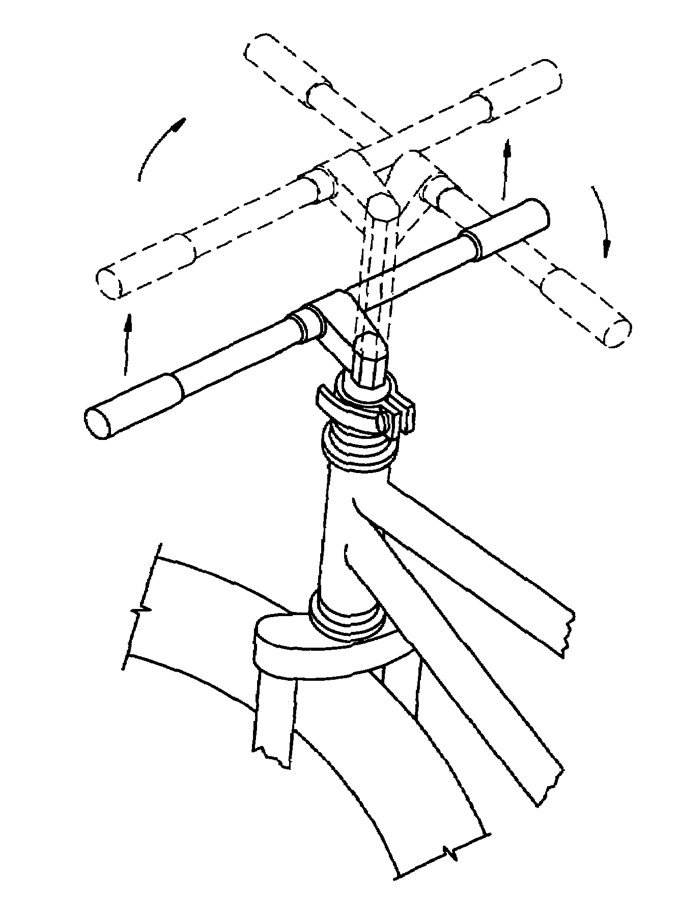
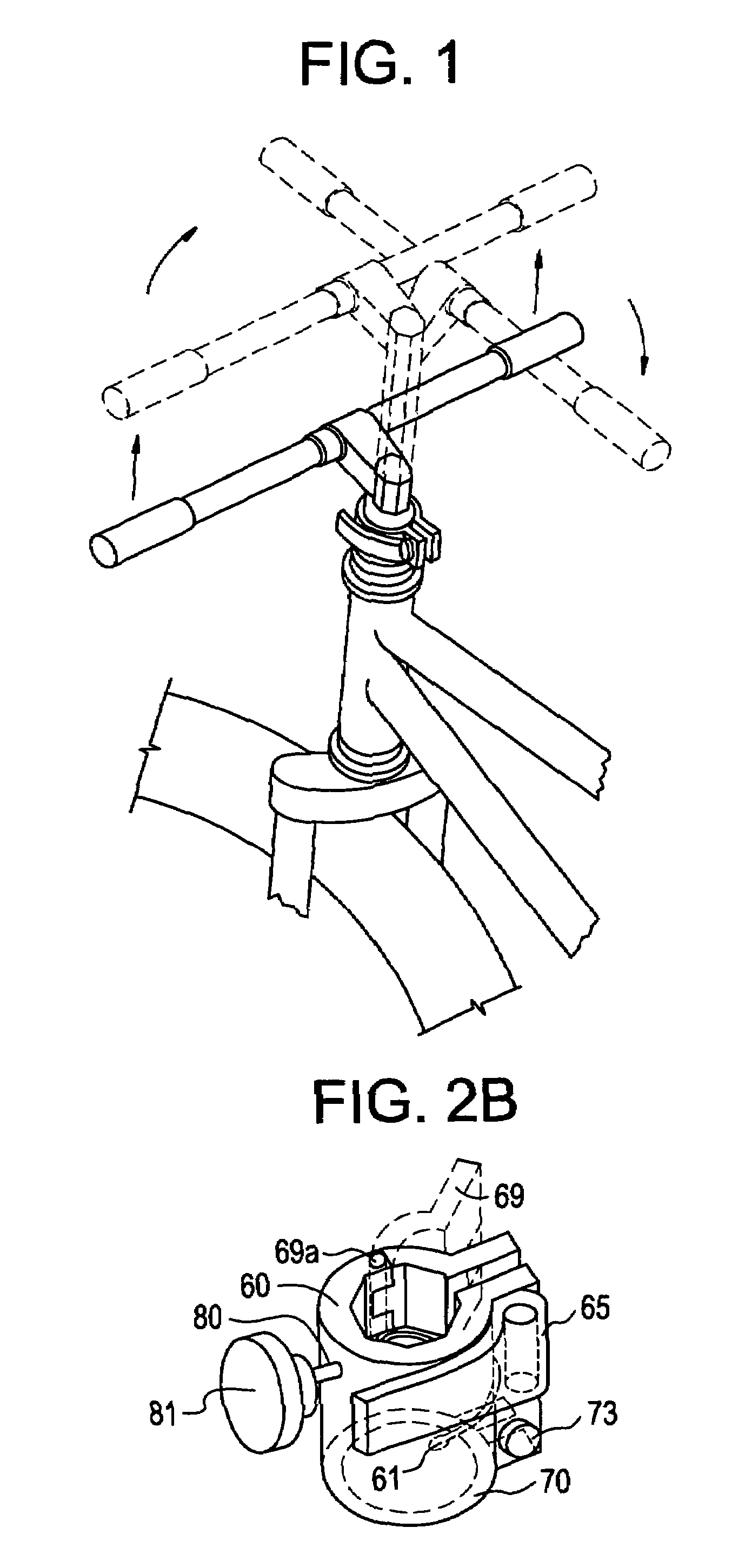
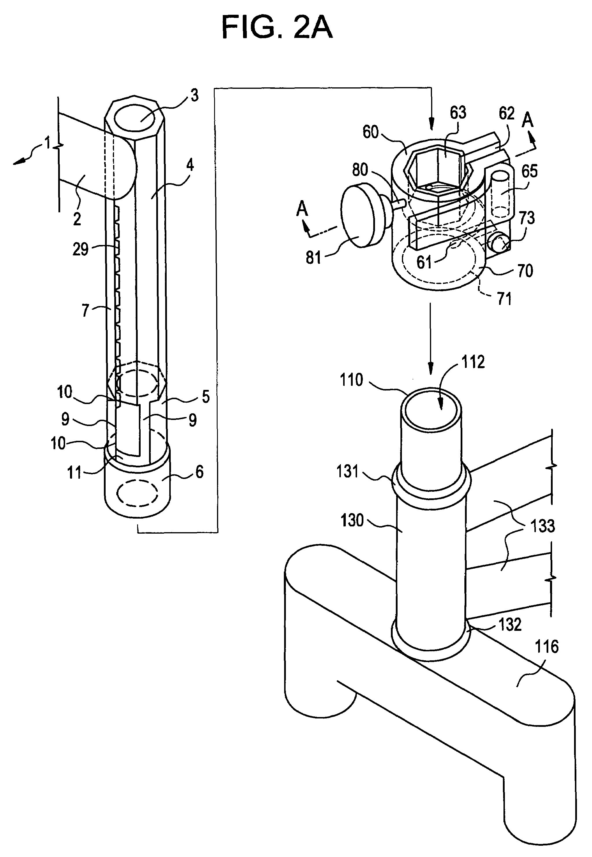
[0110]The steering assemblies of this invention are intended to improve upon existing technology in the two areas—handlebar height adjustability and rotation of the handlebar and stem for easy storage. This invention relates to the method of securing the handlebar stem to the fork steerer tube in a manner that is both safe and convenient for the operator.

[0111]This invention comprises a steering assembly where the handlebar stem is manually moveably fastened to the front fork steerer tube using a primary locking device and requiring a secondary action to allow for movement which comprises of either height adjustment, or rotation, or both. In all cases, even if the primary locking device is unlocked, the secondary locking device or function must be performed in order to allow for rotation.

[0112]In the figures, the steering assembly use a standard handlebar, usually not shown, a stem which attaches to the handlebar on one end and either mounts inside or outside of a front fork steerer...


PUM


Abstract

An apparatus and method of securing a bicycle handlebar stem to the front wheel fork steerer tube with handlebar height adjustability and rotation of the handlebar and stem for easy storage. A steering assembly is provided where the handlebar stem is moveably fastened to the front fork steerer tube using a manually operated primary locking device and requiring a secondary action to allow for movement in the form of either height adjustment, or rotation, or both. The connection between the handlebar stem and the front fork steerer tube can be on the interior or the exterior of the front fork steerer tube. With the interior connection, the steerer tube can be elongated to extend above the top of the headset bearings where it is fitted with a collar for clamping onto the internally mounted stem. The handlebar stem and fork steerer tube are fitted with corresponding octagonal or other cross sectional shapes, or a safety tracking system. For bicycles equipped with handlebar stems which clamp to the outside of the fork steerer tube, the handlebar stem is equipped with a safety lock and can be rotated for storage with no height adjustability.

Description

[0001]This is a continuation application of U.S. application Ser. No. 10 / 769,774 filed Feb. 3, 2004 now abandoned. The entire disclosure of the prior application, is hereby incorporated by reference.I. BACKGROUND OF THE INVENTION[0002]a. Field of the Invention[0003]This invention relates to the steering assembly on bicycles. In particular, this invention relates to the method and apparatus of securing a bicycle handlebar stem to the front wheel fork steerer tube in a manner that is both safe and convenient for the operator. The steering assemblies of this invention are intended to improve upon existing technology in the two areas—handlebar height adjustability and rotation of the handlebar such that the handlebars end up parallel to the front wheel and the vehicle frame for easy storage.[0004]b. Prior Art[0005]Bicycles are often used only occasionally and stored frequently for extended periods of time. Yet, due to the laterally protruding handlebars, storage is not particularly conv...

Claims


Application Information

Patent Timeline
Patent Type & Authority Patents(United States)
IPC IPC(8): B62K21/00B62H5/06B62K15/00B62K21/22F16D1/02F16D1/04
CPCB62K21/22B62K15/00
Inventor MONTAGUE, DAVIDMONTAGUE, HARRY
Owner MONTAGUE CORP
Why Eureka
Try Eureka