Pivot bushing for a variable-pitch vane of a turbomachine

a technology of variable pitch vane and guide pivot, which is applied in the direction of sliding contact bearings, machines/engines, liquid fuel engines, etc., can solve the problems of less effective operation of the centering pivot of the vane, and achieve the effect of reducing such drawbacks

Active Publication Date: 2007-03-15
SN DETUDE & DE CONSTR DE MOTEURS DAVIATION S N E C M A
View PDF5 Cites 30 Cited by
  • Summary
  • Abstract
  • Description
  • Claims
  • Application Information

AI Technical Summary

Benefits of technology

[0006] A main object of the present invention is to thus to mitigate such drawbacks by presenting a bushing that is suitable for ensuring permanent centering quality for vane guide pivots, regardless of the conditions under which the turbomachine is operating and independently of the materials used for making the bushing and the inner ring in which the bushing is mounted.

Problems solved by technology

Unfortunately, known mounts for bushings in the inner ring do not include any particular arrangement for ensuring that the quality of the centering is maintained.
The centering of the vane guide pivot thus tends to become less effective in operation, in particular when the pivot support bushings and the inner ring are made of materials that present different coefficients of thermal expansion.

Method used


Image

  • Pivot bushing for a variable-pitch vane of a turbomachine
  • Pivot bushing for a variable-pitch vane of a turbomachine
  • Pivot bushing for a variable-pitch vane of a turbomachine

Examples


Embodiment Construction

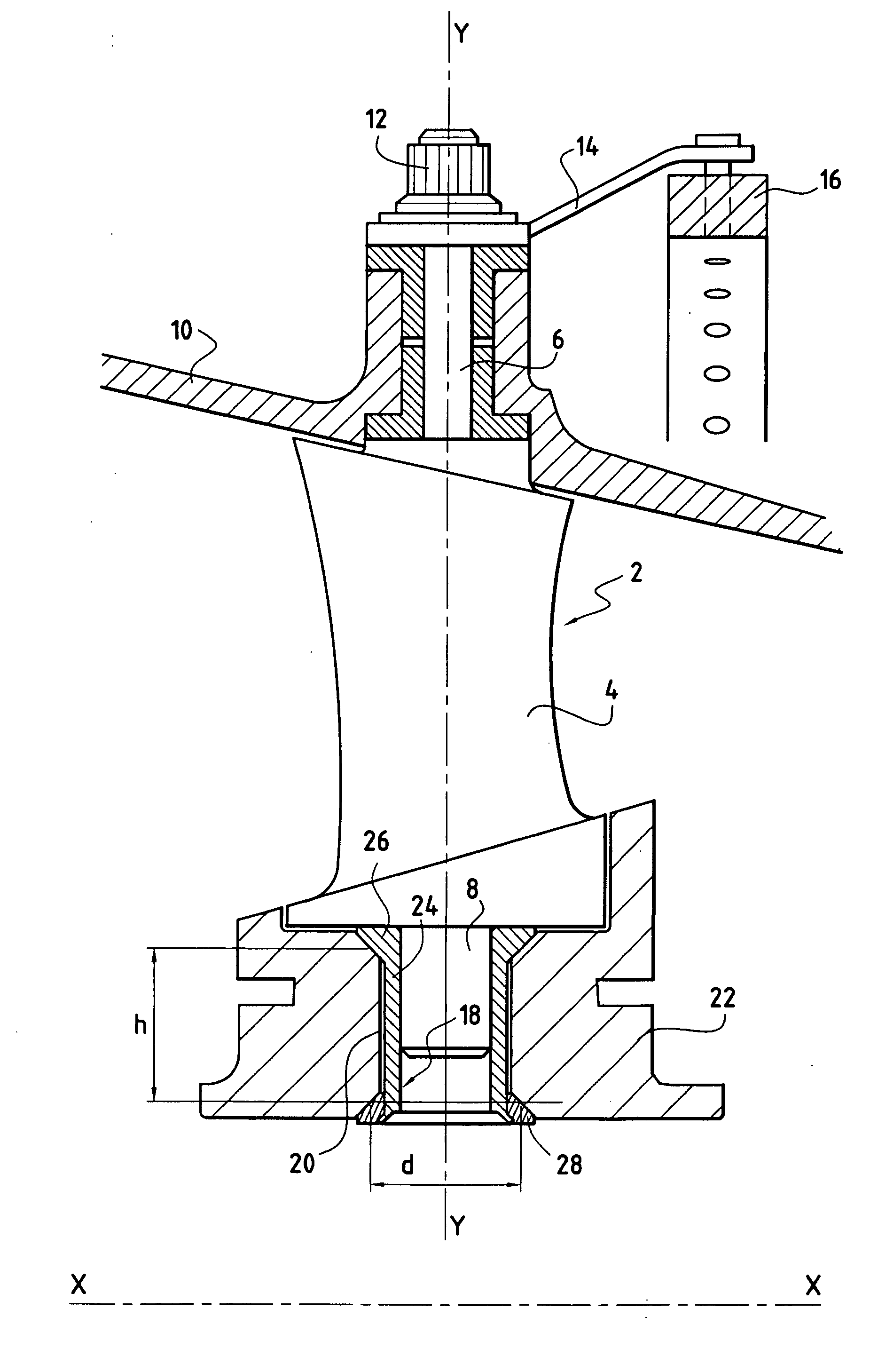
[0024] With reference to FIG. 1, the variable-pitch vanes 2 of the high pressure compressor of the turbomachine are distributed in circular stages centered on the longitudinal axis X-X of the turbomachine and they are disposed between stages of moving blades (not shown) which are secured on a rotor of the turbomachine.

[0025] Each variable-pitch vane 2 of a circular stage extends along a main axis Y-Y that is radial in direction relative to the longitudinal axis X-X of the turbomachine. The vane 2 is in the form of an airfoil 4 terminating at a radially outer end (or vane head) in a control pivot 6 (or top pivot) and at a radially inner end (or vane root) in a guide pivot 8 (or bottom pivot).

[0026] The control pivot 6 of the variable-pitch vane 2 centered on its main axis Y-Y passes through an annular stator casing 10 of the turbomachine and co-operates with a control member for varying the pitch of the vanes. More precisely, the control pivot 6 of each vane 2 projects radially to ...


PUM


Abstract

A pivot bushing for a variable-pitch vane of a turbomachine, the bushing being for mounting in a recess in a ring of the turbomachine, the recess being of a shape that is substantially complementary to the shape of the bushing. The bushing comprises a substantially tubular body of longitudinal axis provided at one end with a first conical collar and at an opposite end with a second conical collar, the conical surfaces defined by the first and second collars being disposed facing each other.

Description

BACKGROUND OF THE INVENTION [0001] The present invention relates to the general field of variable-pitch vanes for turbomachines, and more particularly to bushings for the guide pivots of such vanes. [0002] The high pressure compressor of a turbomachine having a gas turbine typically comprises a plurality of circular stages of vanes of pitch orientation that can be adjusted in order to modify the gas flow characteristics depending on the operating speed of the turbomachine. Such vanes are referred to as variable-pitch vanes. [0003] Each variable-pitch vane in a given stage has a respective control pivot at its head and a guide pivot at its root. The control pivot passes through a stator casing of the turbomachine and co-operates with a control member. By acting on said control member, it is possible to vary the orientation of the vanes in the corresponding stage. The guide pivot of each vane is movable in a bushing mounted in a corresponding recess in an inner ring of the turbomachin...

Claims


Application Information

Patent Timeline
Patent Type & Authority Applications(United States)
IPC IPC(8): F04D29/56
CPCF01D17/162F04D29/057F04D29/563F05D2250/232F16C33/04F05D2260/74F05D2230/64F16C17/10
Inventor BOURU, MICHEL ANDRE
Owner SN DETUDE & DE CONSTR DE MOTEURS DAVIATION S N E C M A
Why Eureka
Try Eureka