Structure for avalanche improvement of ultra high density trench MOSFET

a technology of trench mosfet and structure, which is applied in the direction of semiconductor devices, basic electric elements, electrical equipment, etc., can solve the problems of poor metal coverage, unreliable electrical contact, and difficulty, and achieve the effect of reducing body resistance, reducing body resistance, and increasing cell density

Inactive Publication Date: 2006-12-07
M MOS SEMICON
View PDF15 Cites 31 Cited by
  • Summary
  • Abstract
  • Description
  • Claims
  • Application Information

AI Technical Summary

Benefits of technology

[0010] It is therefore an object of the present invention to provide new and improved processes to form a more reliable source contact metal layer with smaller CD to allow for higher cell density and also for surrounding the source contact trench with doped region to reduce the body resistance such that the above-discussed technical difficulties of limited avalanche capability may be resolved.
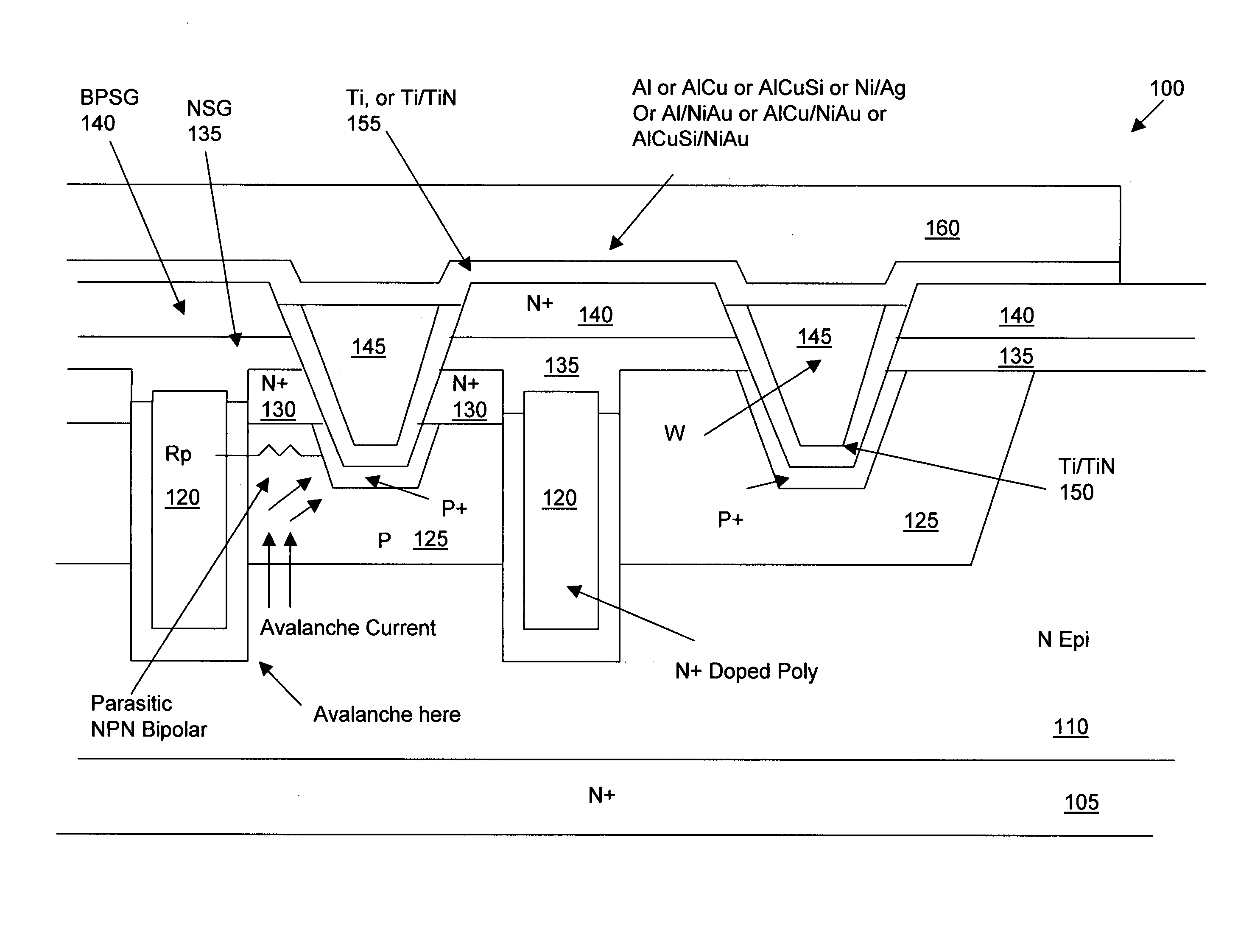
[0011] Specifically, it is an object of the present invention to provide a new and improved cell configuration and fabrication process to form a source metal contact by opening a source-body contact trench by applying an oxide etch followed by a silicon etch. The source-body contact trench then filled with a metal plug to assure reliable source contact is established. The source-body contact trench is further surrounded with doped region to reduce the body resistance between the source-body contact trench and the trenched gate to avoid turning on the parasitic NPN bipolar with higher avalanche current. The new and improved MOSFET configurations can therefore overcome the problems and limitations encountered by the conventional semiconductor power devices.
[0012] Another aspect of the present invention is to further increase the avalanche capability by forming a buried region doped with a first conductivity type under the body regions to direct the avalanche current directly from the buried regions to the source-body contact. The drain-to-source resistance is reduced and the avalanche capability is further enhanced.
[0013] Briefly, in a preferred embodiment, the present invention discloses a trenched metal oxide semiconductor field effect transistor (MOSFET) cell that includes a trenched gate surrounded by a source region encompassed in a body region above a drain region disposed on a bottom surface of a substrate. The MOSFET cell further includes a source-body contact trench opened with sidewalls substantially perpendicular to a top surface into the source and body regions and filled with contact metal plug. A body-resistance reduction region doped with body-doped is formed to surround the source-body contact trench to reduce a body-region resistance between the source-body contact metal and the trenched gate to improve an avalanche capability. In a preferred embodiment, the contact metal plug further comprising a Ti / TiN barrier layer surrounding a tungsten core as a source-body contact metal. In another preferred embodiment, the MOSFET cell further includes an insulation layer covering a top surface over the MOSFET cell wherein the source body contact trench is opened through the insulation layer. And, the MOSFET cell further includes a thin resistance-reduction conductive layer disposed on a top surface covering the insulation layer and contacting the contact metal plug whereby the resistance-reduction conductive layer having a greater area than a top surface of the contact metal plug for reducing a source-body resistance. In another preferred embodiment, the contact metal plug filled in the source body contact trench comprising a substantially cylindrical shaped plug. In another preferred embodiment, the MOSFET cell further includes a thick front metal layer disposed on top of the resistance-reduction layer for providing a contact layer for a wire or wireless bonding package. In an alternate preferred embodiment, the source-body contact trench having stepwise sidewalls and said contact metal plug filled in said source-body contact trench comprising a substantially cup shaped plug having a wider top contact area. In a preferred embodiment, the MOSFET device further includes a doped buried region disposed below the body region for improving the avalanche capability and the drain to source resistance of the MOSFET device.
[0014] This invention further discloses a method for manufacturing a trenched metal oxide semiconductor field effect transistor (MOSFET) cell comprising a step of forming said MOSFET cell with a trenched gate surrounded by a source region encompassed in a body region above a drain region disposed on a bottom surface of a substrate. The method further includes a step of covering the MOSFET cell with an insulation layer and applying a contact mask for opening a source-body contact trench with sidewalls substantially perpendicular to a top surface of the insulation layer into the source and body regions. The method further includes a step of forming a body-resistance-reduction region by implanting a body-resistance-reduction-dopant in the body region immediately near the source-body contact trench whereby an avalanche capability of the MOSFET cell is enhanced. In a preferred embodiment, the step of implanting the body-resistance-reduction-dopant is a step of implanting a dopant of a same conductivity type as a body dopant doped in the body region. In a preferred embodiment, the step of forming the body-resistance-reduction region further includes a step of forming the body-resistance-reduction region surrounding a bottom portion of the source-body contact trench. In a preferred embodiment, the step of forming the body-resistance-reduction region further comprising a step of forming the body-resistance-reduction region immediately below a bottom of the source-body contact trench. In a preferred embodiment, the step of opening the source-body contact trench further comprising a step of opening the source-body contact trench with the sidewalls converging with a small tilted angle relative to a perpendicular direction to the top surface of the substrate. In a preferred embodiment, the method further includes a step of forming a buried region by implanting source-dopant ions below the body region for further enhancing the avalanche capability.

Problems solved by technology

Conventional technologies of forming aluminum metal contact to the N+ source and P-well formed in the P-body regions in a semiconductor device is encountering a technical difficulty of poor metal coverage and unreliable electrical contact when the cell pitch is shrunken.
The technical difficulty is especially pronounced when a metal oxide semiconductor field effect transistor (MOSFET) cell density is increased above 200 million cells per square inch (200 M / in2) with the cell pitch reduced to 1.8 um or to even a smaller dimension.
The metal contact space to both N+ source and P-well in the P-body regions for cell density higher than 200M / in2 is less than 1.0 um, resulting in poor metal step coverage and high contact resistance to both N+ and P-body region.
The device performance is adversely affected by these poor contacts and the product reliability is also degraded.
Another is poor metal step coverage due to high aspect ratio of contact height and open dimension.
Even that the contact CD (Critical Dimension) can be shrunk without significantly increasing contact resistance, however, the single metal contact to the source region vertically has the drawback that it is difficult to further shrink the critical dimension due to the single metal contact structure.
Particularly, the contact CD is limited by the problem of aluminum metal step coverage that often occurs when the depth to width ratio of the V-groove is increased as a result of further shrinking of the cell size.
Moreover, because of the self-aligned contact without leaving enough space between the trench gate and the V-groove contact, the P+ may touch the channel region causing high threshold voltage Vth issue.
Another limitation of conventional MOSFET device that has a cell density higher than 200 million cells per square inch (200 M / in2) is the limited avalanche current due to the concerns of inadvertent triggering parasitic N+PN bipolar parasitically exists between the source disposed next to the P-body with the P-body further adjacent to the N-epitaxial layer.
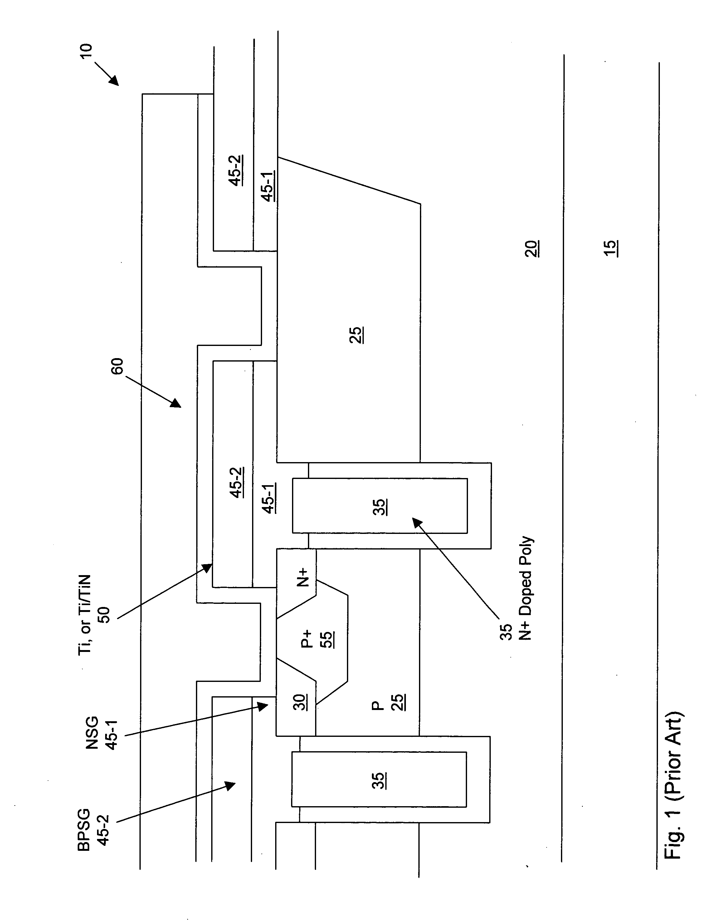
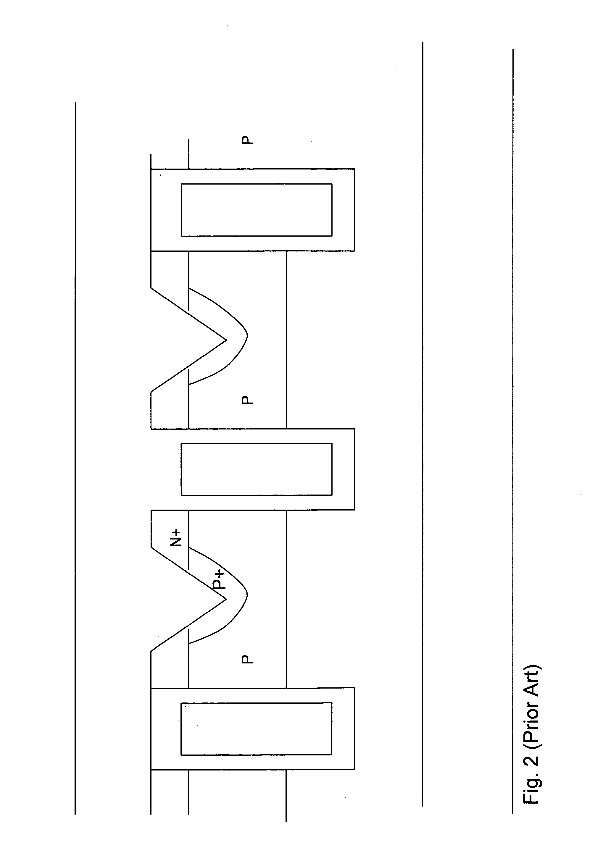
For DC-to-DC applications, even though it is important to increase the avalanche current, the conventional MOSFET devices as shown in FIGS. 1 and 2 are still limited by the requirement to avoid the turning on the parasitic bipolar without having metal step coverage and high Vth issues as result of cell density increase.
Therefore, for the semiconductor power device such as the MOSFET, there are still difficulties to achieve the design goals of increasing the cell density and in the meantime, improving the avalanche capability.

Method used


Image

  • Structure for avalanche improvement of ultra high density trench MOSFET
  • Structure for avalanche improvement of ultra high density trench MOSFET
  • Structure for avalanche improvement of ultra high density trench MOSFET

Examples


Embodiment Construction

[0026] Please refer to FIG. 3 for a first preferred embodiment of this invention where a metal oxide semiconductor field effect transistor (MOSFET) device 100 is supported on a N+ substrate 105 formed with an N epitaxial layer 110. The MOSFET device 100 includes a trenched gate 120 disposed in a trench with a gate insulation layer 115 formed over the walls of the trench. A body region 125 that is doped with a dopant of second conductivity type, e.g., P-type dopant, extends between the trenched gates 120. The P-body regions 125 encompassing a source region 130 doped with the dopant of first conductivity, e.g., N+ dopant. The source regions 130 are formed near the top surface of the epitaxial layer surrounding the trenched gates 125. The top surface of the semiconductor substrate extending over the top of the trenched gate, the P body regions 125 and the source regions 130 are covered with a NSG and a BPSG protective layers 135 and 140 respectively.

[0027] For the purpose of improving...


PUM


Abstract

A trenched metal oxide semiconductor field effect transistor (MOSFET) cell that includes a trenched gate surrounded by a source region encompassed in a body region above a drain region disposed on a bottom surface of a substrate. The MOSFET cell further includes a source-body contact trench opened with sidewalls substantially extend vertically relative to a top surface into the source and body regions and filled with contact metal plug. A body-resistance reduction region doped with body-doped is formed to surround the source-body contact trench to reduce a body-region resistance between the source-body contact metal and the trenched gate to improve an avalanche capability.

Description

[0001] This patent application is a Continuation in Part (CIP) Application of a co-pending application Ser. No. 11 / 147,075 filed by a common Inventor of this Application on Jun. 6, 2005. The Disclosures made in that Application is hereby incorporated by reference.BACKGROUND OF THE INVENTION [0002] 1. Field of the Invention [0003] This invention relates generally to the cell structure and fabrication process of power semiconductor devices. More particularly, this invention relates to a novel and improved cell structure and improved process for fabricating a trenched semiconductor power device with improved avalanche capability. [0004] 2. Description of the Prior Art [0005] Conventional technologies of forming aluminum metal contact to the N+ source and P-well formed in the P-body regions in a semiconductor device is encountering a technical difficulty of poor metal coverage and unreliable electrical contact when the cell pitch is shrunken. The technical difficulty is especially prono...

Claims


Application Information

Patent Timeline
Patent Type & Authority Applications(United States)
IPC IPC(8): H01L29/78H01L21/336
CPCH01L24/26H01L24/40H01L24/45H01L24/49H01L24/83H01L24/85H01L29/41766H01L29/456H01L29/66727H01L29/66734H01L29/7813H01L2224/05624H01L2224/05655H01L2224/45015H01L2224/45124H01L2224/45144H01L2224/48247H01L2224/48472H01L2224/48624H01L2224/48655H01L2224/48724H01L2224/48755H01L2224/4903H01L2224/49051H01L2224/49111H01L2224/83801H01L2224/85H01L2924/01005H01L2924/01013H01L2924/01014H01L2924/01015H01L2924/01018H01L2924/01022H01L2924/01027H01L2924/01028H01L2924/01029H01L2924/01042H01L2924/01047H01L2924/0105H01L2924/01074H01L2924/01079H01L2924/04941H01L2924/13091H01L2924/20755H01L2924/2076H01L2924/30105H01L2924/01023H01L2924/01033H01L2924/0132H01L2924/0133H01L2924/1306H01L2924/1305H01L2924/00014H01L2924/00H01L2224/37144H01L2224/37124H01L2224/37147H01L2224/37155H01L2224/371H01L24/37H01L24/48H01L2224/73221
Inventor HSHIEH, FWU-IUAN
Owner M MOS SEMICON
Why Eureka
Try Eureka