Three dimensional construct for the design and fabrication of physiological fluidic networks

a fluid network and three-dimensional technology, applied in the field of tissue engineering, design and fabrication of biological constructs, can solve the problems of limited three-dimensional integration of the distribution of the vessel network size, the inability to build the elements on the size scale of the capillary, and the limitation of the available space for small blood vessels, so as to increase the lateral dimension. the effect of the number

Active Publication Date: 2012-04-03
MASSACHUSETTS INST OF TECH +2
View PDF35 Cites 32 Cited by
  • Summary
  • Abstract
  • Description
  • Claims
  • Application Information

AI Technical Summary

Benefits of technology

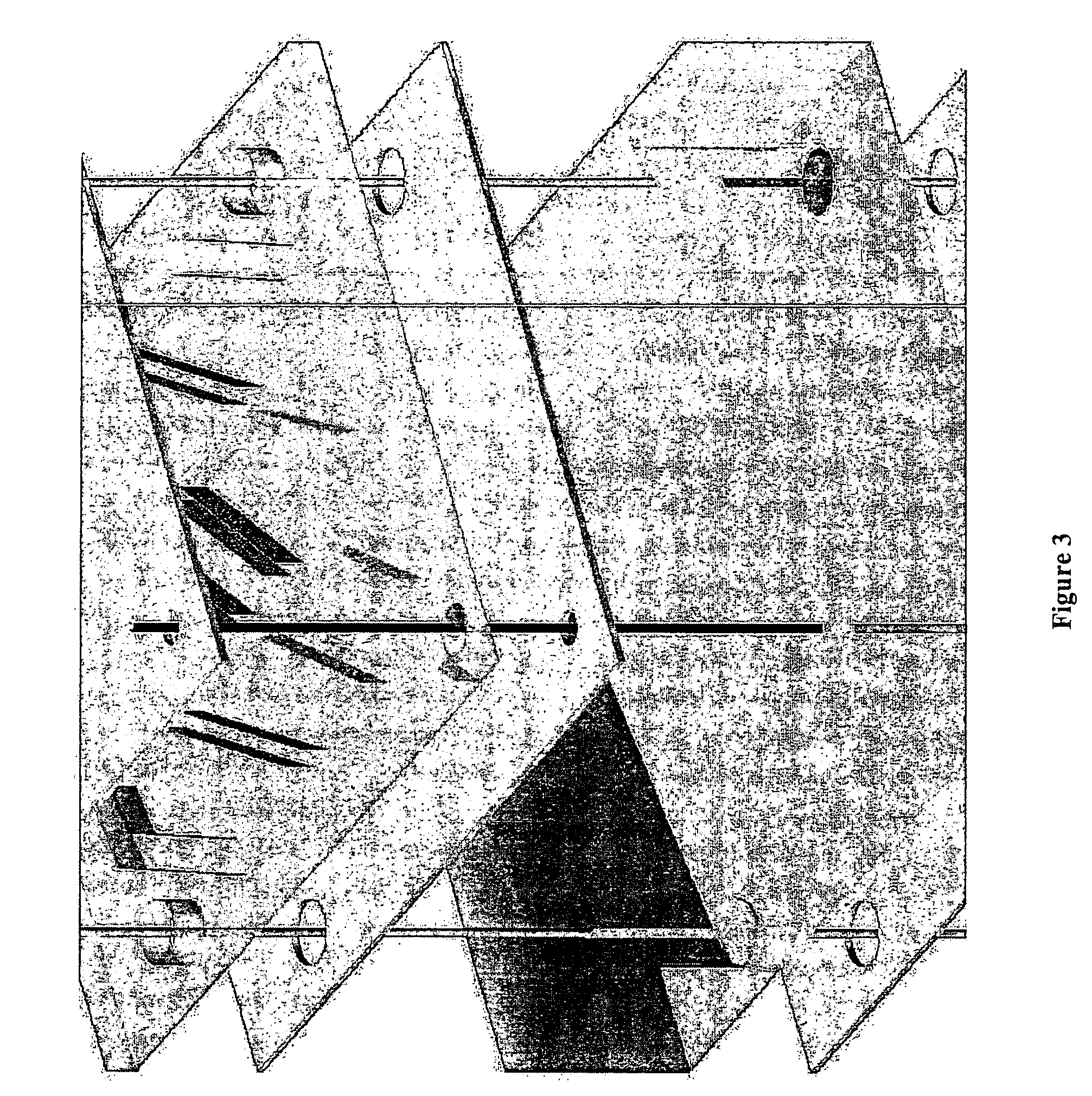
[0013]Current techniques utilize a single vertical link between two dimensional networks at the largest vessel diameter for the inlet and outlet, resulting in alternating horizontal sheets of vessels and unpatterned polymer stacked in the vertical dimension. The present invention provides complex methods of integrating the two dimensional networks, in which small and midsized vessels are arranged to link the networks vertically in a more complex manner. Methods, compositions and devices of the present invention enable higher cell densities and a larger relative number of small vessels to be incorporated into the three dimensional structure of tissue engineered constructs.
[0015]The resulting three-dimensional structure is comprised of a large number of two-dimensional layers, arranged in a repeating fashion, and are stacked vertically in a total stack of at least 15 layers. The present invention can comprise between about 50 and 2000 layers, more preferably between about 100 and 1000 layers and most preferably about 500 layers. Advantageously, designs of the present invention have increased space in the lateral dimension, enabling a much larger number of small channels. It enables at least one order of magnitude but not more than two orders of magnitude increase in the number of small channels.

Problems solved by technology

Initially, tissue engineered constructs were built using solid freeform fabrication technology, however, elements on the size scale of capillaries could not be built.
However, with this method, distribution of vessel network sizes is limited in three-dimensional integration.
Branching networks are not truly three-dimensional, and vessels larger than the capillaries take up a large amount of available space within the two dimensional networks.
This restraint imposes a limitation on the available space for small blood vessels, and as a result, the tissue engineered constructs suffer from non-physiological pressures and fluid velocities.

Method used


Image

  • Three dimensional construct for the design and fabrication of physiological fluidic networks
  • Three dimensional construct for the design and fabrication of physiological fluidic networks
  • Three dimensional construct for the design and fabrication of physiological fluidic networks

Examples


example 1

[0221]The most basic characteristic to evaluate in determining whether a fluidic network is desirable for the design of vasculature in a tissue engineered construct is the number of small vessels provided by the network (e.g., diameter less than about 20 microns). Most mass transfer from the blood to the tissue occurs through small vessels, and a large portion of the network's overall resistance lies in the small vessels. Thus, a network with too few small vessels will generally not provide adequate mass transfer to sustain the tissue, and will have too high a resistance to exist in the cardiovascular system. One advantage of the design method provided by the present invention is that networks can have vessel populations matching those of physiological systems, allowing the design of a true vasculature system. Using the diameter-defined Strahler ordering system (Jiang et al., Journal Of Applied Physiology 76 (2):882 (1994)), the number of vessels in a Hextak can be compared to physi...


PUM

PropertyMeasurementUnit
size distributionaaaaaaaaaa
diameteraaaaaaaaaa
diameteraaaaaaaaaa

Abstract

The present invention relates to methods for the design and fabrication of biological constructs, such as organ simulants or organ replacements, which contain complex microfluidic architecture. Designs of the present invention provide increased space in the lateral dimension, enabling a large number of small channels for small vessels.

Description

RELATED APPLICATIONS[0001]This application is filed under 35 U.S.C. §371 as the U.S. national phase application of International Application PCT / US03 / 029880, having an international filing date of Sep. 23, 2003 and designating the U.S. and claiming priority from U.S. application Ser. No. 60 / 412,981, filed on Sep. 23, 2002, and U.S. application Ser. No. 60 / 449,291, filed on Feb. 21, 2003, the contents of which are incorporated herein by reference.[0002]Reference is made herein to U.S. Ser. No. 10 / 187,247, a CIP of U.S. Ser. No. 10 / 187,247, filed Jun. 28, 2002, which claims priority to U.S. Ser. No. 60 / 367,675, filed Mar. 25, 2002, and which is a CIP of Ser. No. 09 / 560,480, filed Apr. 28, 2000, which claims priority to U.S. Ser. No. 60 / 165,329, filed Nov. 12, 1999 and to U.S. Ser. No. 60 / 131,930, filed Apr. 30, 1999, the contents each of which are expressly incorporated herein by reference.[0003]Each of the foregoing applications and patents and articles, and each document cited or re...

Claims


Application Information

Patent Timeline
Patent Type & Authority Patents(United States)
IPC IPC(8): A61F2/02A61BB01L3/00C12M3/00C12N5/00C12N5/06G01F1/00G01F1/28G01N15/06
CPCC12M25/14C12N5/0062G06F19/3437B01L3/5027B33Y80/00G16H50/50Y10T137/206Y10T137/212
Inventor VACANTI, JOSEPH P.BORENSTEIN, JEFFREYKAAZEMPUR-MOFRAD, MOHAMMAD R.WEINBERG, ELI
Owner MASSACHUSETTS INST OF TECH
Why Eureka
Try Eureka