Valve gear of internal combustion engine

a technology of internal combustion engine and valve gear, which is applied in the direction of machines/engines, valve drives, non-mechanical valves, etc., can solve the problems of increasing electric motor ratings and electric power consumption, and achieve the effect of reducing torque, reducing torque fluctuation, and reducing the output required for electric motors for driving the cam mechanism

Inactive Publication Date: 2006-06-06
TOYOTA JIDOSHA KK
View PDF9 Cites 8 Cited by
  • Summary
  • Abstract
  • Description
  • Claims
  • Application Information

AI Technical Summary

Benefits of technology

[0006]Accordingly, an object of the present invention is to provide a valve gear of an internal combustion engine which can restrict a rated power required for an electric motor for driving a cam mechanism and an electric power consumption thereof.
[0007]In order to achieve the object mentioned above, according to the present invention, there is provided a valve gear of an internal combustion engine comprising a cam mechanism for converting rotational motion of an electric motor into linear motion to drive a valve for opening and closing a cylinder against a valve spring, and a torque reduction mechanism for adding an opposite torque serving so as to reduce a torque applied to the cam mechanism from the valve spring at the time of driving the valve, to the cam mechanism.
[0008]In the valve gear according to the present invention, the torque periodically fluctuating in synchronous with the opening and closing motion of the valve is applied to the cam mechanism, at the time of opening and closing the valve against a reaction force of the valve spring. The torque reduction mechanism applies the opposite torque canceling the torque to the cam mechanism, whereby it is possible to reduce the torque applied as a load to the electric motor and is possible to restrict the fluctuation thereof.
[0009]In the valve gear according to the present invention, the torque reduction mechanism may comprise an opposite phase cam which rotates in an interlocking manner at a rotational speed of 1 / N (where N is an integral number) times of the rotational speed of a cam in the cam mechanism and has a cam surface formed on a surface thereof, a cam holding member which is in contact with the cam surface, and an urging member which urges the cam holding member toward the cam surface of the opposite phase cam, and an outline of the cam surface on the opposite phase cam may be set such that an opposite torque canceling a valve spring torque applied to the cam mechanism based on the reaction force of the valve spring is applied to the opposite phase cam from the urging member. According to the structure mentioned above, it is possible to add the opposite torque canceling the valve spring torque, based on a simple structure of arranging the opposite phase cam, bringing the holding member into contact with the cam surface on the surface of the opposite phase cam and pressing by the urging member.
[0010]Further, the torque reduction mechanism may comprise an opposite phase cam which rotates in an interlocking manner at a rotational speed of 1 / N (where N is an integral number) times of the rotational speed of a cam in the cam mechanism and has a cam surface formed on an outer periphery thereof, a cam holding member which is in contact with the cam surface, and an urging member which urges the cam holding member toward the cam surface on the opposite phase cam, and an outline of the cam surface on the opposite phase cam may be set such that an opposite torque canceling a combined torque obtained by combining a valve spring torque applied to the cam mechanism based on the reaction force of the valve spring and an inertia toque applied to the cam mechanism according to motion of the valve is applied to the opposite phase cam from the urging member. In this case, since the opposite torque is set taking the inertia torque into consideration, it is possible to restrict the fluctuation of the torque applied as the load to the electric motor smaller. Accordingly, it is possible to improve a control accuracy of the valve at the time of high rotation of the internal combustion engine when the inertia toque is particularly increased, and it is possible to accurately control an intake or exhaust property of the internal combustion engine to a target property. Even at the time of low rotation, it is possible to change an operation property of the intake valve or the exhaust valve in a more opening direction, thereby allowing an intake efficiency or an exhaust efficiency to sufficiently be improved at the time of low rotation.
[0015]According to the present invention, since the torque applied to the cam mechanism from the valve spring can be reduced by the opposite torque which the torque reduction mechanism applies to the cam mechanism, it is possible to reduce the torque applied to the electric motor as a load, and it is possible to restrict the fluctuation of the torque. Accordingly, the output required to the electric motor for driving the cam mechanism can be reduced, the electric power consumption of the electric motor can be restricted, and the rated output required for the electric motor can be lowered. Therefore, it is possible to use a compact electric motor in comparison with the case that the torque reduction mechanism is omitted.

Problems solved by technology

Accordingly, when the valve spring torque is increased, an increase of an electric power consumption and an increase of an electric motor rating are generated.

Method used


Image

  • Valve gear of internal combustion engine
  • Valve gear of internal combustion engine
  • Valve gear of internal combustion engine

Examples


first embodiment

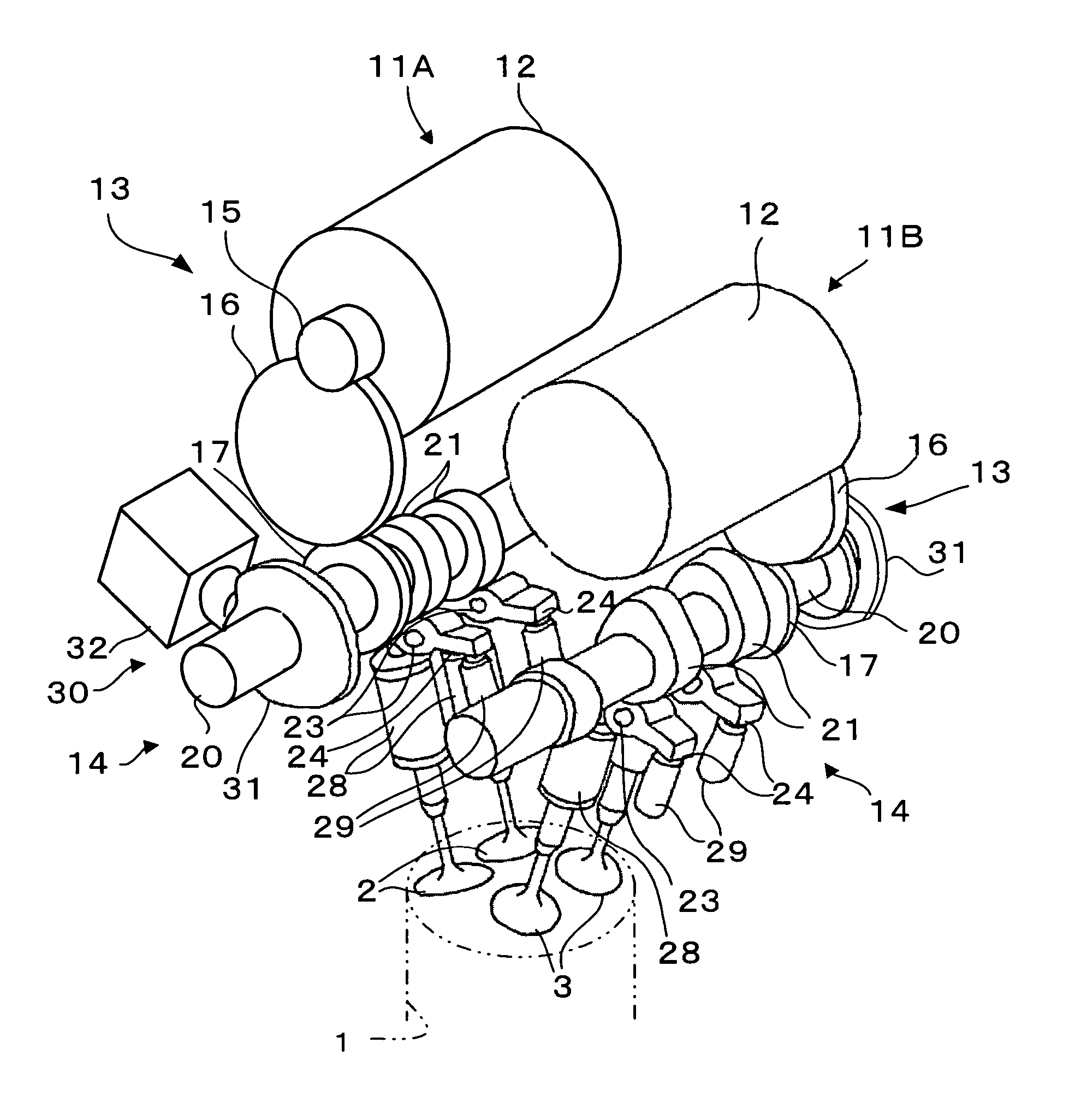
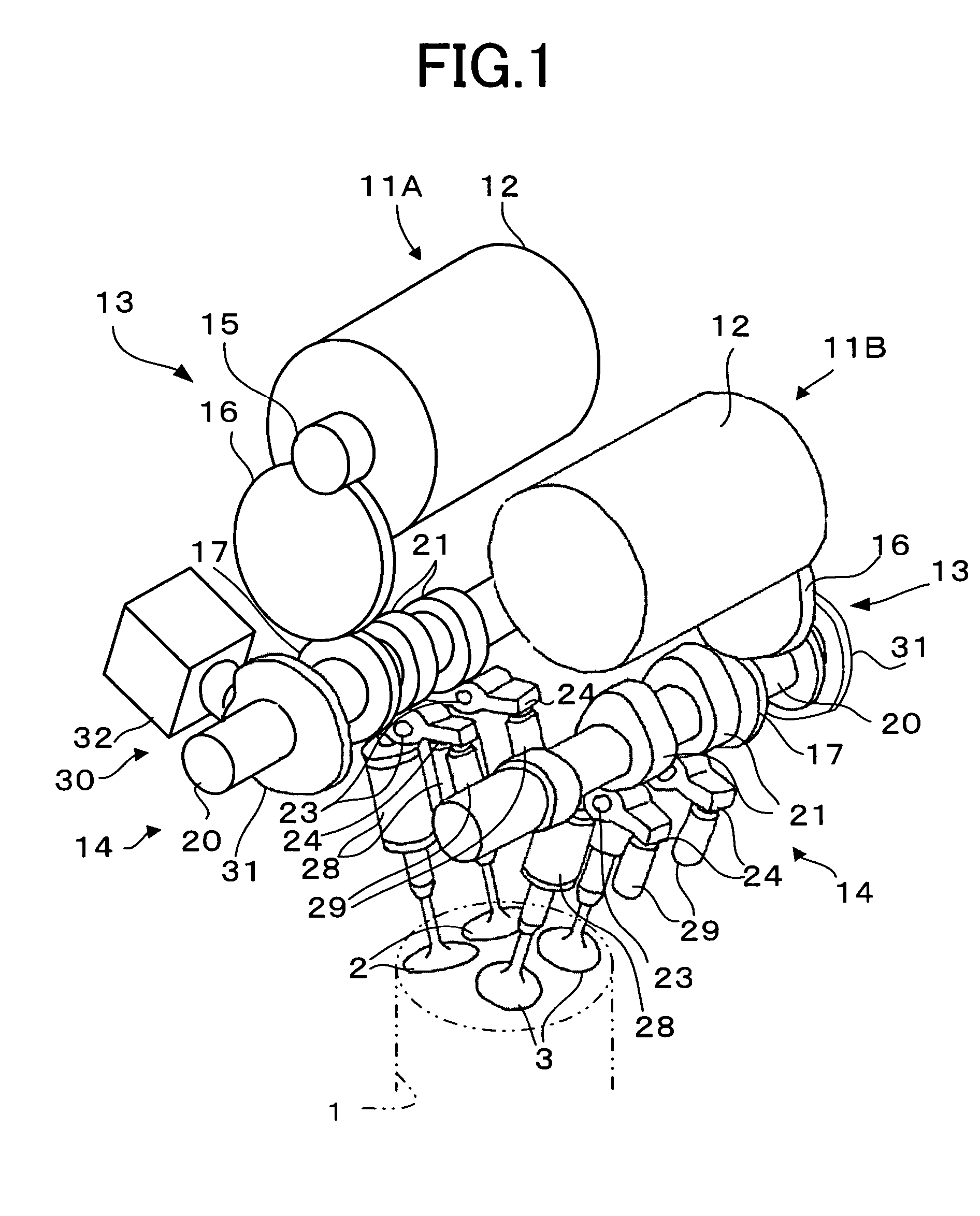
[0027]FIG. 1 shows an embodiment of a valve gear according to the present invention. Valve gears 11A and 11B in FIG. 1 are installed in a multiple cylinder reciprocal type internal combustion engine. In the internal combustion engine, two intake valves 2 of one cylinder 1 are driven by one valve gear 11A, and two exhaust valves 3 of the same cylinder 1 are driven so as to be opened and closed by another valve gear 11B. With regard to the other cylinders (not shown), the intake valves and the exhaust valves are driven so as to be opened and closed by the different valve gears 11A and 11B in the same manner. The valve gear 11A in an intake side and the valve gear 11B in an exhaust side basically have the same structure, and a description will be given below of the valve gear 11A in the intake side.

[0028]The valve gear 11A in the intake side is provided with an electric motor (hereinafter, referred to as a motor) 12 serving as a drive source, a gear train 13 corresponding to a transfer...

second embodiment

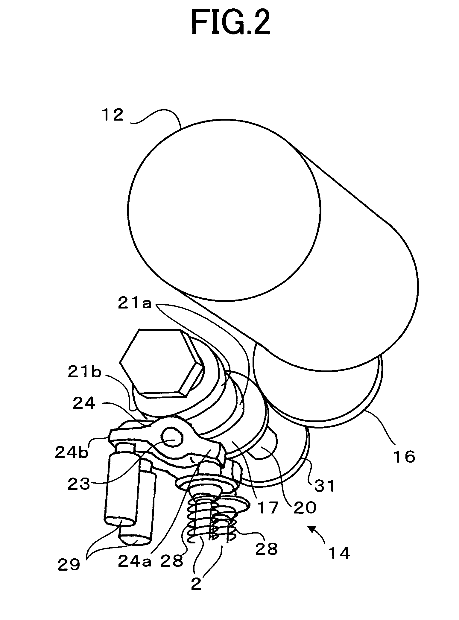
[0043]Next, a description of the second embodiment according to the present invention will be given with reference to FIGS. 6 to 8. According to the second embodiment, the cam profile of the opposite phase cam 31 is designed while taking into consideration an inertia force of a reciprocating part at the time when the intake valve 2 or the exhaust valve 3 is driven so as to be opened and closed. In this case, the mechanical structure of the valve gears 11A and 11B is the same as the first embodiment.

[0044]In the case of opening and closing the intake valve 2 or the exhaust valve 3 via the cam mechanism 14, the rocker arm 24, the valve spring 28 and the like are reciprocated according to the motion of the valve 2 or 3, whereby the inertia force is generated, and the inertia torque is applied to the cam mechanism 14 in addition to the valve spring torque. When the rotational speed of the internal combustion engine is low, the inertia toque is sufficiently small in comparison with the v...


PUM


Abstract

There is provided a valve gear of an internal combustion engine, comprising a cam mechanism for converting rotational motion of an electric motor into linear motion to drive a valve for opening and closing a cylinder against a valve spring, and a torque reduction mechanism for adding an opposite torque, which serves so as to reduce a torque applied to the cam mechanism from the valve spring at the time of driving the valve, to the cam mechanism.

Description

BACKGROUND OF THE INVENTION[0001]1. Field of the Invention[0002]The present invention relates to a valve gear of an internal combustion engine.[0003]2. Description of the Related Art[0004]An intake valve and an exhaust valve of an internal combustion engine are driven so as to be opened and closed by a power taken out from a crank shaft of the internal combustion engine. In recent years, it is tried to drive the intake valve and the exhaust valve by an electric motor to open and close the valves. For example, there has been proposed a valve gear which opens and closes the intake valve by rotating a cam shaft by a stepping motor (Japanese Patent Application Laid-Open (JP-A) No. 8-177536). In addition, JP-A No. 59-68509 exists as a prior art document relevant to the present invention.[0005]When the intake valve and the exhaust valve are opened and closed by driving the cam mechanism by the electric motor, it is necessary to output a driving force against a torque applied to the cam me...

Claims


Application Information

Patent Timeline
Patent Type & Authority Patents(United States)
IPC IPC(8): F01L1/04F01L9/20F01L1/00F01L1/08F01L9/22
CPCF01L1/08F01L9/04F01L2009/0411F01L9/22F01L9/20
Inventor KUSAKA, YASUSHIASADA, TOSHIAKIEZAKI, SHUICHITSUJI, KIMITOSHI
Owner TOYOTA JIDOSHA KK
Why Eureka
Try Eureka