Rotary polishing device for inner wall of bearing bush

A bearing pad inner and rotating shaft technology, which is applied in the field of bearing pad inner wall rotary grinding device, can solve the problems of low work efficiency, inconvenient fixing, and human hazards caused by debris, and achieve the effect of preventing shaking

Active Publication Date: 2021-08-17
江苏益达管件股份有限公司
View PDF8 Cites 2 Cited by
  • Summary
  • Abstract
  • Description
  • Claims
  • Application Information

AI Technical Summary

Problems solved by technology

[0005] In order to overcome the inconvenience of fixing the inner wall of the bearing pad by the general grinding equipment, the general grinding method is to manually grind the bearing pads one by one, resulting in low work efficiency, and the debris generated by grinding will cause harm to the human body. Disadvantages, the technical problem of the present invention is to provide a rotary grinding device for the inner wall of the bearing bush that can be fixed and quickly polished, and can clean up the debris generated during grinding and facilitate collection

Method used


Image

  • Rotary polishing device for inner wall of bearing bush
  • Rotary polishing device for inner wall of bearing bush
  • Rotary polishing device for inner wall of bearing bush

Examples


Embodiment 1

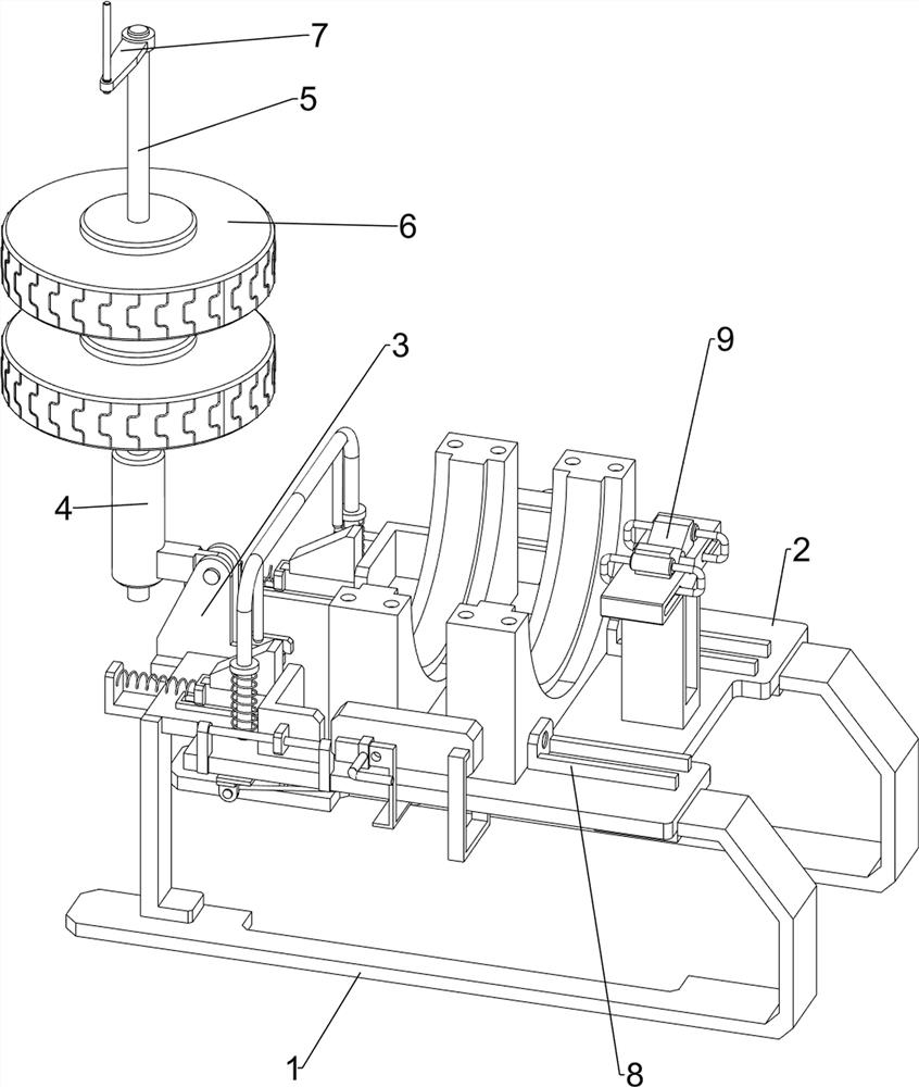
[0027] like figure 1 As shown, a shaft venetical wall rotating grinding device includes a bottom plate 1, a support plate 2, a first bearing housing 3, a rotating shaft sleeve 4, a straight axle 5, a grinding disc 6, a handle 7, a placed mechanism 8, and a locking mechanism 9, A support plate 2 is provided on the bottom plate 1, and the first bearing housing 3 is provided on the left side of the support plate 2. The first housing 3 is provided with a rotating shaft sleeve 4, and the rotating shaft sleeve 4 is rotated. 5 The straight shaft 5 is symmetrically provided with a grinding disc 6, and the vertical rotating shaft 5 is provided with a handle 7, and a placed mechanism 8 is provided on the support plate 2, and a locking mechanism 9 is provided on the right side of the support plate 2.

[0028] When grinding the inner wall of the shaft watt, the staff is placed on the support plate 2, and then the worker rotates the rotating shaft sleeve 4 to rotate downward on the first housi...

Embodiment 2

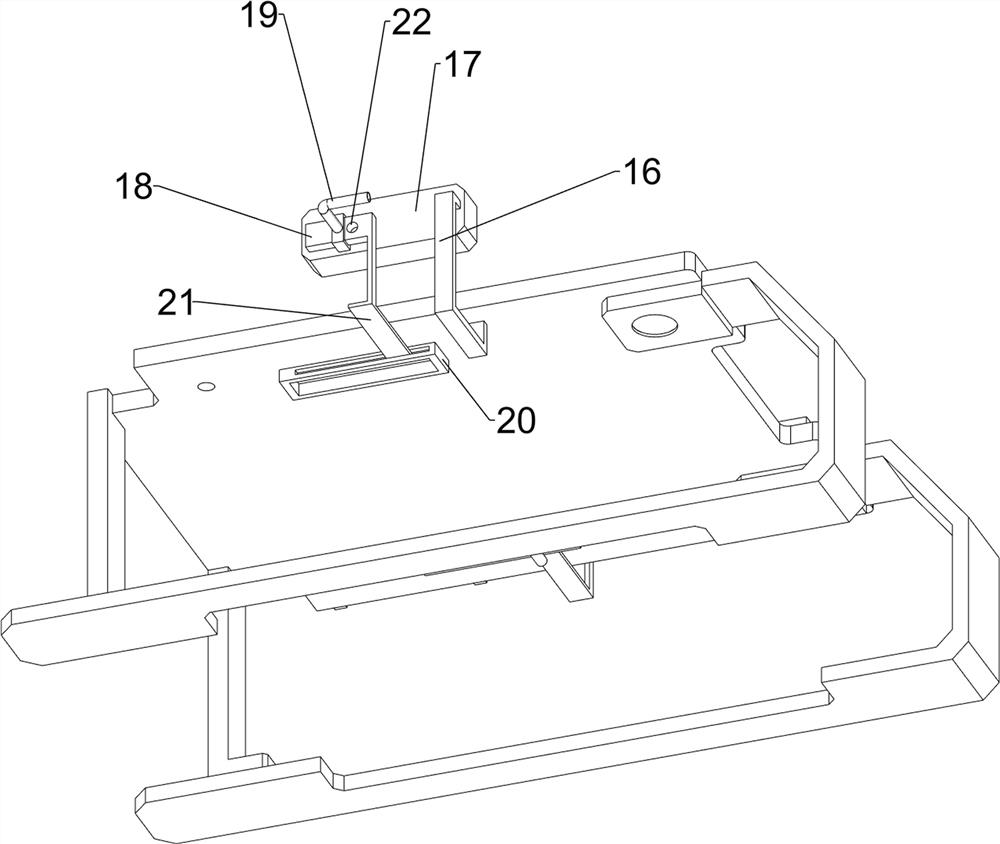
[0030] like figure 2 and image 3 As shown, on the basis of Example 1, the placement mechanism 8 includes a first fixing block 81, a guide bar 82, a first slider 83, a second fixing block 84, a first slide plate 85, and a second slider. 86. The first fixing block 81 is provided on the right side of the support plate 2, and the left side of the support plate 2 is configured with the guide bar 82, and the two guide bar 82 slide, and there is a first slider 83, two first slides. A second fixing block 84 is provided on the block 83, and the left side of the support plate 2 is configured with a first slide plate 85, and the two first slot plate 85 has a second sliding block 86, two first The two slider 86 is connected to the two second fixed block 84 side.

[0031] When the rotating shaft sleeve 4 is rotated downward to rotate downward, the staff pushes the second slider 86 to slide to the right in the first slot plate 85, and the second sliding block 86 slides to the right to drive the...

Embodiment 3

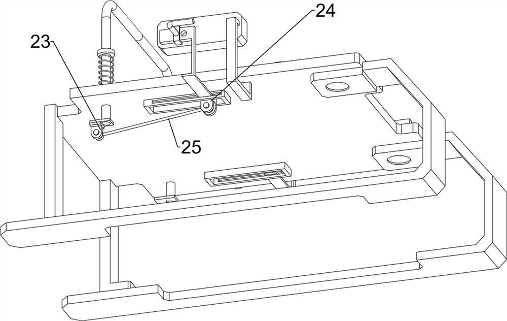
[0035] like Figure 4 , Figure 5 and Image 6 The second slider 10, the second elastic member 11, the fixing rod 12, and the second wedge block 13 are also included. The left side sliding type provided with the support plate 2 has a second slider 10, and the second slider 10 is two. A second elastic member 11 is provided between the front and rear sides of the support plate 2, and the upper portion of the second slider 10 is provided with a fixed bar 12, and the two second sliding blocks 86 are provided with a second wedge block 13, two. The second wedge block 13 is fitted to the two fixing rods 12.

[0036] When the rotating sleeve 4 is rotated downward to rotate downward, the straight shaft 5 is rotated downward to contact the second slider 10, and the second slider 10 is extruded, the second elastic member 11 is compressed, The second slider 10 moves down the second wedge block 13 toward down the second wedge block 13, and the second wedge block 13 moves the second slider 86 to t...


PUM


Abstract

The invention relates to a polishing device, in particular to a rotary polishing device for an inner wall of a bearing bush. According to the rotary polishing device for the inner wall of the bearing bush, fixing and rapid polishing can be conducted, chippings generated during polishing can be cleared, and collection is convenient. The rotary polishing device for the inner wall of the bearing bush comprises a bottom plate and a first bearing block, wherein a supporting plate is arranged on the bottom plate, and the first bearing block is arranged on the supporting plate. After the bearing bush is placed on the supporting plate, a rotating shaft sleeve rotates downwards on the first bearing block by rotating, the rotating shaft sleeve rotates downwards and drives a straight rotating shaft to rotate downwards, a placing mechanism moves rightwards to fix the bearing bush, the straight rotating shaft rotates downwards to extrude a locking mechanism to move away from the straight rotating shaft, the straight rotating shaft is locked through resetting of the locking mechanism, and then a handle is rotated to drive the straight rotating shaft to rotate on the rotating shaft sleeve, the straight rotating shaft rotates to drive a millstone to rotate, and the millstone rotates to polish the inner wall of the bearing bush.

Description

Technical field [0001] The present invention relates to a grinding apparatus, and more particularly to a shaft inner wall rotating grinding device. Background technique [0002] The shaft tile is part of the sliding bearing and the journal in contact with the "shaft liner", the shape is a tile semi-cylindrical surface, and the shaft is usually paired, and the two shaft tapes are circular, and the inner side of the shaft is The journal is slidable, and the smoothness of the inner wall directly affects the connection effect of the rotary support. [0003] Therefore, in the process of performing the shaft tabulation, the inner wall of the shaft needle needs to be polished, but due to the shaft tabs to the semi-cylindrical surface, the general grinding device is fixed in the process of grinding the inner wall of the shaft, generally polished by manual pair tabs. It is grinded by one by one, and the efficiency of work is low, and the debris grinding is harmful to the human body. [00...

Claims


Application Information

Patent Timeline
Patent Type & Authority Applications(China)
IPC IPC(8): B24B5/10B24B27/00B24B41/06B24B47/00B24B47/10B24B55/06B24B55/12
CPCB24B5/10B24B27/0076B24B41/06B24B47/00B24B47/10B24B55/06B24B55/12Y02P70/10
Inventor 范和菊
Owner 江苏益达管件股份有限公司
Why Eureka
Try Eureka