Reinforcing steel bar sleeve grouting device

A steel sleeve and slurry technology, which is applied to structural elements, building components, building reinforcements, etc., can solve the problems of increased construction procedures, cumbersome operations, and increased construction costs, and achieve simplified construction procedures, improved connection strength, and reduced The effect of engineering expenditure

Pending Publication Date: 2021-08-17
SHANGHAI SIPAI AUTOMATION INSTR ENGCO
View PDF0 Cites 2 Cited by
  • Summary
  • Abstract
  • Description
  • Claims
  • Application Information

AI Technical Summary

Problems solved by technology

However, because the concrete slurry is easy to condense, and the strength after condensing is relatively high, the valve will be firmly bonded to the installation position, so that the repeated use of the valve cannot be realized, resulting in a serious increase in construction costs
At the same time, the installation of the valve increases the construction process, the operation is cumbersome and wastes manpower and material resources, so it is not conducive to the promotion and use in construction projects.

Method used


Image

  • Reinforcing steel bar sleeve grouting device
  • Reinforcing steel bar sleeve grouting device
  • Reinforcing steel bar sleeve grouting device

Examples


Embodiment 1

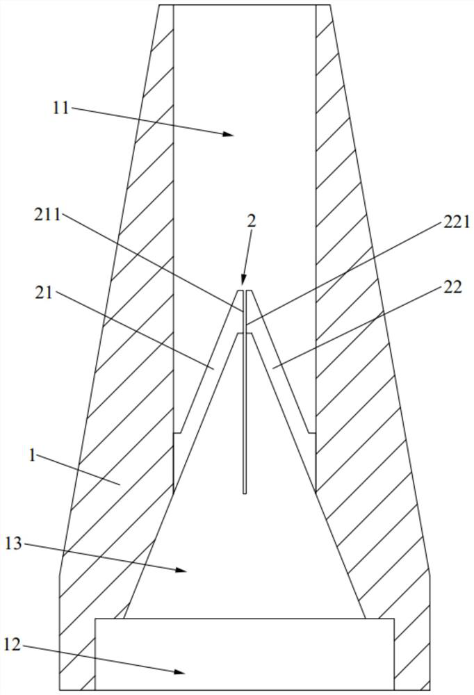
[0038] Such as figure 1 and figure 2 As shown, the present embodiment provides a kind of reinforcing bar sleeve grouting device, comprises grouting pipe plug 1, and one end of grouting pipe plug 1 communicates with the grouting end of grouting equipment, and the other end communicates with reinforcing bar sleeve, that is, injecting The grouting equipment pours concrete grout into the steel bar sleeve through the grouting pipe plug 1, thereby connecting two sections of steel bars.

[0039] The inner wall of the grouting pipe plug 1 is provided with a non-return structure 2. When the grouting equipment grouts into the steel sleeve, the non-return structure 2 is in an open state, so that the concrete slurry in the grouting equipment can pass through the grouting pipe plug smoothly. 1, and enter the reinforcement sleeve; when the reinforcement sleeve is filled with concrete slurry, remove the grouting end of the grouting equipment from the grouting pipe plug 1, at this time, the...

Embodiment 2

[0058] Such as image 3 As shown, this embodiment provides a steel sleeve grouting device, wherein the parts that are the same as or corresponding to those in the first embodiment adopt the reference numerals corresponding to those in the first embodiment. For the sake of brevity, only the difference between Embodiment 2 and Embodiment 1 will be described. The difference is that in this embodiment, the opening of the first valve 21 and the second valve 22 is not realized by the pressure of the concrete slurry, but The pressing force is applied through the grouting equipment, so that the first valve 21 and the second valve 22 are elastically deformed, so as to switch to the open state. Since the concrete slurry is directly pressed against the non-return structure 2 to realize opening, the grouting pressure needs to be increased to a certain extent to ensure that the concrete slurry can press open the first valve 21 and the second valve 22 . In this embodiment, the first valve ...

Embodiment 3

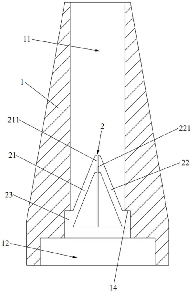
[0064] Such as Figure 4 and Figure 5As shown, this embodiment provides a steel sleeve grouting device, wherein the parts that are the same as or corresponding to those in the first embodiment adopt the reference numerals corresponding to those in the first embodiment. For the sake of brevity, only the difference between Embodiment 3 and Embodiment 1 will be described. The difference is that in this embodiment, the opening of the first valve 21 and the second valve 22 is directly abutting against the first valve through the grouting equipment. 21 and the second valve 22, so that both are elastically deformed, thereby switching to the open state.

[0065] Optionally, in this embodiment, the non-return structure 2 is integrally formed with the grouting pipe plug 1 . see Figure 4 , the end of the first valve 21 and the second valve 22 away from the steel pipe sleeve is the contraction clamping end 212 . When grouting, the grouting end of the grouting equipment is directly i...


PUM


Abstract

The invention belongs to the technical field of building construction, and discloses a reinforcing steel bar sleeve grouting device. The reinforcing steel bar sleeve grouting device comprises a grouting pipe plug, wherein a non-return structure is arranged on the inner wall of the grouting pipe plug, when grouting equipment is used for grouting a reinforcing steel bar sleeve, the non-return structure is in an open state, so that concrete slurry in the grouting equipment smoothly passes through an inner cavity of the grouting pipe plug, concrete slurry can entering the reinforcing steel bar sleeve, when the reinforcing steel bar sleeve is filled with concrete slurry, the grouting end of the grouting equipment is moved away from the grouting pipe plug, at the moment, the non-return structure automatically recovers to the closed state, so that the concrete slurry in the reinforcing steel bar sleeve is prevented from flowing back and leaking through the inner cavity of the grouting pipe plug, it is guaranteed that the compactness of the slurry in the reinforcing steel bar sleeve is good, the connecting strength between the components is effectively improved, and the building construction quality and the safety in the building use process are ensured. The non-return structure can timely block the grouting channel after the grouting is stopped, a wooden plug does not need to be additionally inserted or a closable valve does not need to be arranged, the construction process is simplified, and the project cost is reduced.

Description

technical field [0001] The invention relates to the technical field of building construction, in particular to a steel bar sleeve grouting device. Background technique [0002] At present, in the construction process of prefabricated buildings, the method of steel sleeve grouting is mainly used to realize the connection between various components. Specifically, the two sections of steel bars are connected by a steel bar sleeve, and the steel bar sleeve is set on the ends of the two sections of steel bars, and the prepared concrete slurry is poured into the steel bar sleeve with a grouting gun, and after the concrete slurry solidifies , the two sections of steel bars can be firmly connected together. [0003] In order to ensure that the connection strength between components meets the technical requirements, it is necessary to ensure the compactness of the grouting, that is, the fullness of the concrete slurry in the steel sleeve. However, in the actual construction process...

Claims


Application Information

Patent Timeline
Patent Type & Authority Applications(China)
IPC IPC(8): E04C5/16
CPCE04C5/165
Inventor 蒋宇晨王佳玮徐弢高文翔闵睿
Owner SHANGHAI SIPAI AUTOMATION INSTR ENGCO
Why Eureka
Try Eureka