A multi-stage feeding pneumatic conveying device

A pneumatic conveying and feeding technology, which is applied in the field of pneumatic conveying devices and multi-stage feeding pneumatic conveying devices, can solve the problems of low feeding height, wide feeding range, and large feeding volume, so as to avoid blocking the discharge port , avoid material backflow, and meet the effect of large feeding volume

Active Publication Date: 2017-04-26
NANJING AGRI MECHANIZATION INST MIN OF AGRI
View PDF5 Cites 0 Cited by
  • Summary
  • Abstract
  • Description
  • Claims
  • Application Information

AI Technical Summary

Problems solved by technology

However, the following problems exist in the use of air locks: 1) perfect sealing measures are required, and the structure is relatively complicated; 2) additional working power needs to be provided; 3) it is easy to cause damage to materials, and when the amount of materials is large, it will cause blockage; 4) it needs to occupy certain space
In addition, a small number of pressure-feeding pneumatic conveying devices without air locks must have a sufficient distance between the feeding port and the conveying pipeline to ensure that the stable flow enters the conveying pipeline, so the volume is huge
[0004] In addition, because the material is inevitably mixed with debris such as broken branches, broken seedlings and residual film, it is more likely to cause blockage of the discharge port, resulting in the inability of the material to be continuously and smoothly conveyed
[0005] So far, there is no good solution to solve the problem of wide feeding range, low feeding height and large feeding volume

Method used


Image

  • A multi-stage feeding pneumatic conveying device
  • A multi-stage feeding pneumatic conveying device
  • A multi-stage feeding pneumatic conveying device

Examples


Embodiment 1

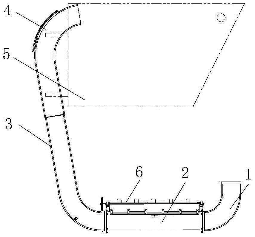
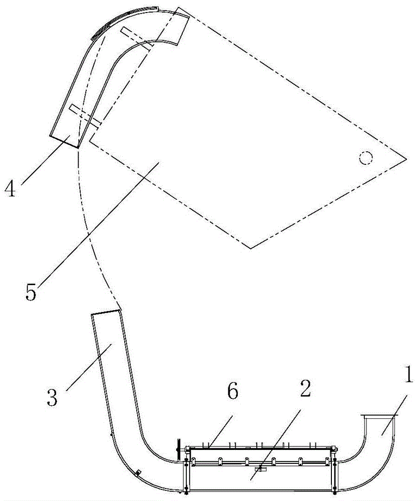
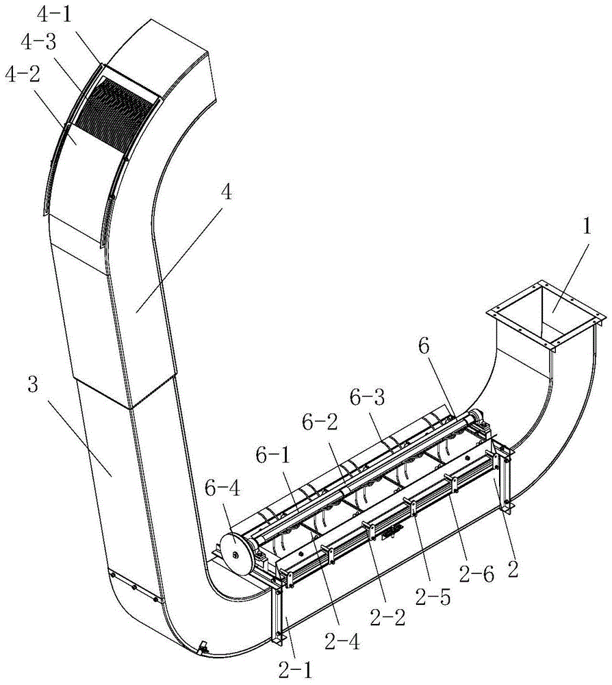
[0026] The basic structure of the multi-stage feeding pneumatic conveying device in this embodiment is as follows: figure 1 As shown, it includes a 90° elbow air inlet pipe 1 connected between the air inlet end and the air outlet of the fan. The upper end of 3 is plugged and communicated with the material throwing pipe 4 . The outlet of the throwing pipe 4 is fixedly connected with the fruit box 5 tops hinged on the loading vehicle, and its lower end is inserted on the feeding pipe 3, so as figure 2 As shown, it can be unloaded together with the fruit box.

[0027] Feeder 2 such as image 3 , 4 As shown in , 5, the main body is a pipe groove 2-1 with a feeding port on the top, and the opening of the pipe groove 2-1 blanking port supports five rotating shafts 2-2 perpendicular to the material conveying direction at intervals, and the rotating shaft 2- 2. Fix the guide block 2-3 whose section is a right-angled trapezoid. The specific structure of diversion block 2-3 is as ...


PUM


Abstract

The invention relates to a multistage feeding pneumatic conveying device and belongs to the technical field of agricultural harvest machinery. The device comprises an air inlet end and an air inlet pipe communicated with an air outlet of a fan. The air outlet end of the air inlet pipe is connected with the lower end of a material conveying pipe through a material falling device which is arranged horizontally. The upper end of the material conveying pipe is communicated with a material throwing pipe. The main body of the material falling device is a tubular tank with the upper portion provided with a feeding port. Position-adjustable rotating shafts which are perpendicular to the material conveying direction are supported at the open portion of a material falling port of the tubular tank at intervals. A guide block is fixed to the rotating shafts. One side of the guide block is fixed to a jet plate. The height of the jet plate decreases gradually in the material conveying direction. A grass shifting shaft parallel to the material conveying direction is supported above the middle of the tubular tank. The grass shifting shaft extends out of anti-winding blades and shifting fingers in the radial direction, and the shifting fingers are distributed at intervals in the axial direction and stretch out in the radial direction, so that a grass shifting device is formed. By means of the multistage feeding pneumatic conveying device, it can be guaranteed that materials flow stably, and blockage of the feeding port and backflow of the materials are effectively avoided.

Description

technical field [0001] The invention relates to a pneumatic conveying device, in particular to a multi-stage feeding pneumatic conveying device, which belongs to the technical field of agricultural harvesting machinery. Background technique [0002] Peanut is an important oil crop, and harvesting is an important link in the peanut production process. Peanut mechanized combined harvesting is an important part of realizing the whole mechanization of peanut production. According to the applicant's understanding, combined peanut harvesting can be divided into two types: full-feeding and half-feeding. The full-feeding combined harvesting equipment can complete combined harvesting operations such as peanut picking, fruit picking, cleaning, transportation, and fruit collection at one time. The peanut pod pneumatic conveying device is an important part of the full-feed peanut combined harvesting equipment. During the combined harvesting operation, the peanut material after fruit p...

Claims


Application Information

Patent Timeline
Patent Type & Authority Patents(China)
IPC IPC(8): B65G53/04B65G53/34B65G53/40
Inventor 胡志超于昭洋曹明珠王申莹徐弘博陈有庆顾峰伟吴锋
Owner NANJING AGRI MECHANIZATION INST MIN OF AGRI
Why Eureka
Try Eureka