
Optical element angle fine adjustment mechanism

A technology for fine-tuning angles and optical components, applied in optical components, optics, instruments, etc., can solve the problems of single angle adjustment mechanism and large limitation of angle adjustment range

Active Publication Date: 2021-08-17
宁波法里奥光学科技发展有限公司
View PDF8 Cites 3 Cited by
  • Summary
  • Abstract
  • Description
  • Claims
  • Application Information

AI Technical Summary

Problems solved by technology

[0002]Optical components are the basic components of the optical system. Most of the optical components play the role of imaging, such as lenses, prisms, mirrors, etc., and some are in the optical system Parts that play special roles (such as light splitting, image transmission, filtering, etc.), such as reticles and filters, etc., in order to improve the imaging quality of some optical components, the angle and position of the optical components need to be fine-tuned. The angle adjustment mechanism of the optical element is relatively simple, and the angle adjustment range is limited, which cannot well meet the needs of users. Therefore, we propose a fine-adjustment mechanism for the angle of the optical element

Method used


Image

  • Optical element angle fine adjustment mechanism
  • Optical element angle fine adjustment mechanism
  • Optical element angle fine adjustment mechanism

Examples


Embodiment Construction

[0026] The following will clearly and completely describe the technical solutions in the embodiments of the present invention with reference to the accompanying drawings in the embodiments of the present invention. Obviously, the described embodiments are only some, not all, embodiments of the present invention. Based on the embodiments of the present invention, all other embodiments obtained by persons of ordinary skill in the art without making creative efforts belong to the protection scope of the present invention.

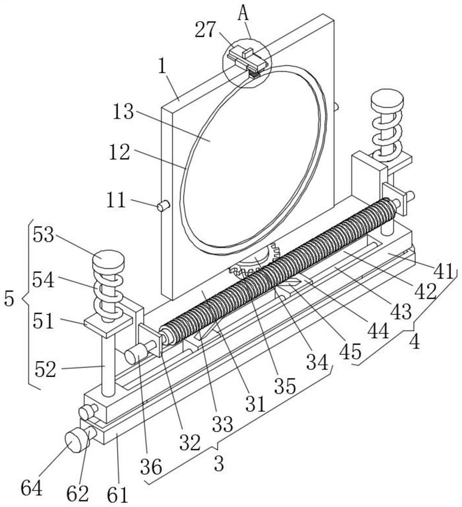
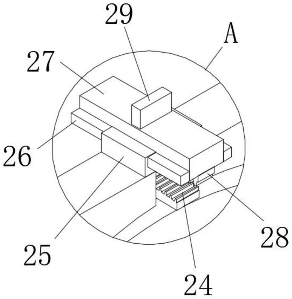
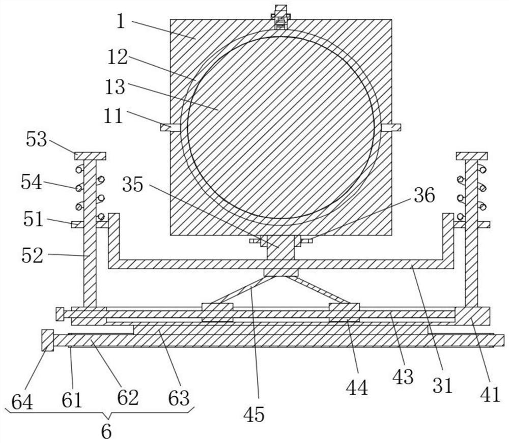
[0027] see Figure 1-4 , this embodiment provides a technical solution: an optical element angle fine-tuning mechanism, including a block 1 and a first angle adjustment assembly 2;

[0028] Box 1: There are pin shafts 11 symmetrically running through the middle of both sides, a round frame 12 is arranged between the pin shafts 11 on both sides, and an optical element 13 is arranged inside the round frame 12, and a second angle adjustment component is arranged ...


PUM


Abstract

The invention discloses an optical element angle fine adjustment mechanism which comprises a square frame and a first angle adjustment assembly. Pin shafts symmetrically penetrate through the middles of the two sides of the square frame, a round frame is arranged between the pin shafts on the two sides, an optical element is arranged in the round frame, a second angle adjusting assembly is arranged at the bottom of the square frame, a height adjusting assembly and a limiting assembly are arranged on the second angle adjusting assembly, and a horizontal adjusting assembly is arranged at the bottom of the height adjusting assembly. The first angle adjusting assembly comprises a middle groove, a limiting shaft, a transmission gear, an arc-shaped plate, a guide rail and a guide rod, the middle groove is formed in the middle of the top face of the square frame, the limiting shaft is arranged in the middle groove, the limiting shaft is movably sleeved with the transmission gear, the arc-shaped plate is arranged at the top of the round frame, and meshing teeth are evenly arranged on the arc face of the arc-shaped plate. According to the optical element angle fine adjustment mechanism, the angle adjustment range can be effectively expanded, the use requirement can be better met, and the practicability is high.

Description

technical field [0001] The invention relates to the technical field of optical element adjustment, in particular to an optical element angle fine adjustment mechanism. Background technique [0002] Optical components are the basic components of the optical system. Most of the optical components play the role of imaging, such as lenses, prisms, mirrors, etc., and some have special functions in the optical system (such as light splitting, image transmission, filtering, etc. Parts, such as reticles and filters, etc., in order to improve the imaging quality of some optical components, the angle and position of the optical components need to be fine-tuned. The angle adjustment mechanism of some existing optical components is relatively simple, and the angle adjustment range is relatively limited. It is too large to meet the needs of users. Therefore, we propose a fine-tuning mechanism for the angle of optical components. Contents of the invention [0003] The technical problem...

Claims


Application Information

Patent Timeline
IPC IPC(8): G02B7/00
CPCG02B7/00
Inventor 高爱平
Owner 宁波法里奥光学科技发展有限公司
Learn More