
Industrial cleaning robot

A technology for cleaning robots and robot bodies, which is applied in the field of robots and can solve problems such as easy loosening and damage of robot parts, lack of anti-collision devices, and affecting service life

Active Publication Date: 2021-08-20
GUIZHOU UNIV OF ENG SCI
View PDF8 Cites 0 Cited by
  • Summary
  • Abstract
  • Description
  • Claims
  • Application Information

AI Technical Summary

Problems solved by technology

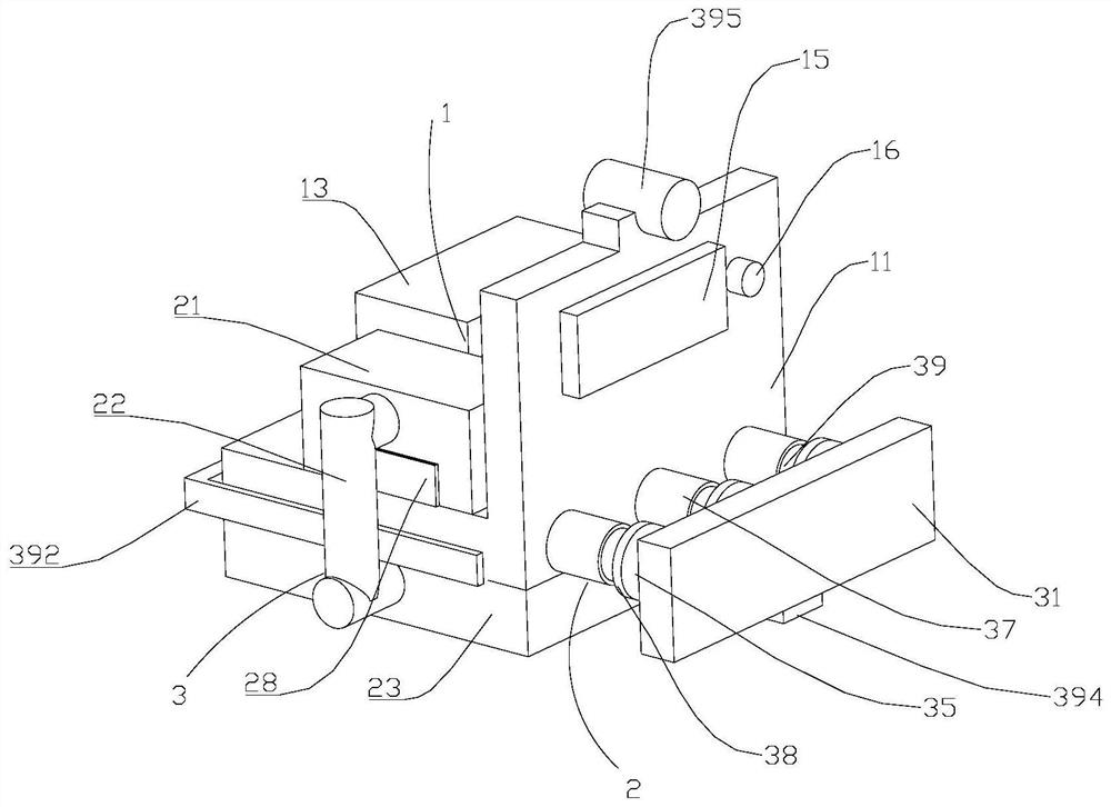
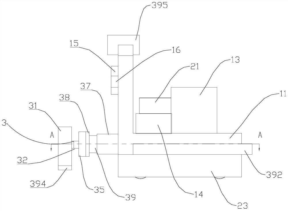
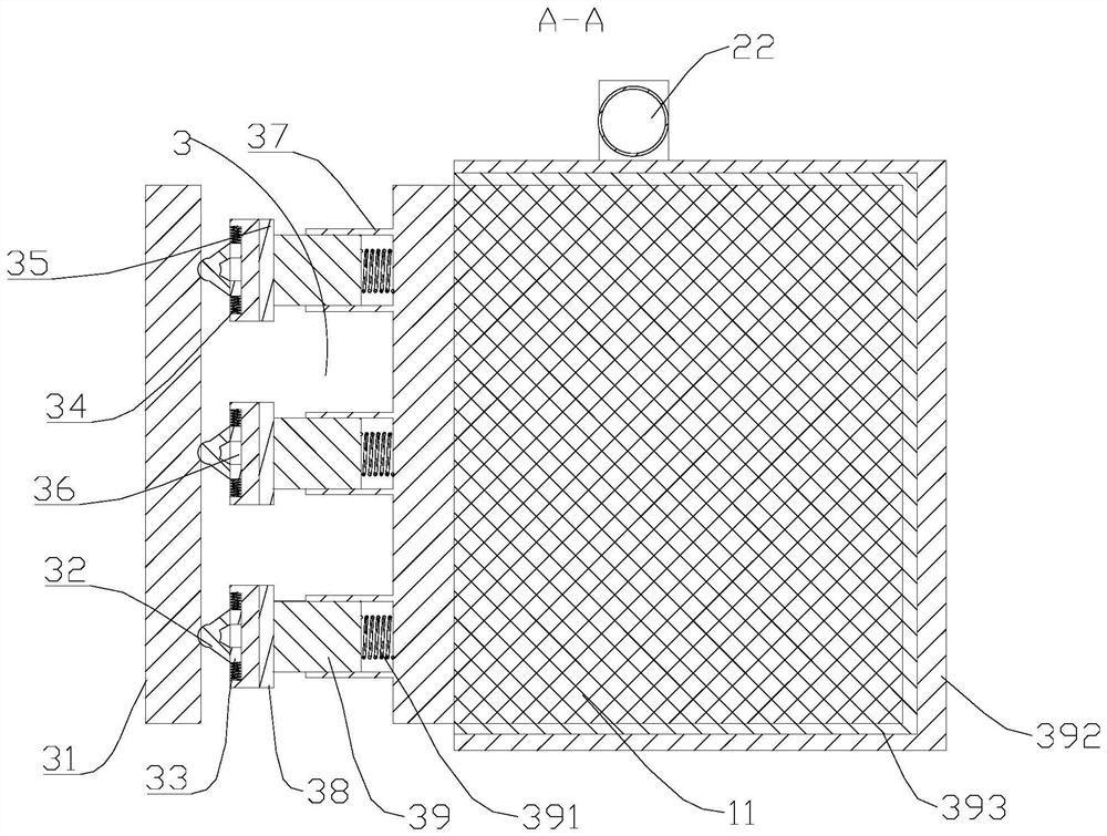
[0004] The purpose of the present invention is to provide an industrial cleaning robot, which aims to solve the problem that the traditional cleaning robot lacks anti-collision devices, and the collision parts of the robot are easy to loosen and damage, which affects the service life.

Method used


Image

  • Industrial cleaning robot
  • Industrial cleaning robot
  • Industrial cleaning robot

Examples


Embodiment Construction

[0022] Embodiments of the present invention will be described in detail below, and examples of the embodiments are illustrated in the drawings, in which the same or similar reference numerals represent the same or similar elements or elements having the same or similar functions. The following is exemplary, and is intended to be used to illustrate the invention without understanding the limitation of the invention.

[0023] In the description of the present invention, it is to be understood that the terms "length", "width", "upper", "lower", "front", "post", "left", "right", "vertical", The orientation of the "horizontal", "top", "bottom", "inside", "outside", etc., is based on the orientation or positional relationship shown in the drawings, is only for ease of describing the invention and simplified description, not Indicating or implying that the device or element must have a specific orientation, constructed and operated in a particular orientation, and thus is not to be const...


PUM


Abstract

The invention relates to the technical field of robots, in particular to an industrial cleaning robot. The robot comprises a robot body, a cleaning assembly and an anti-collision assembly, and the anti-collision assembly comprises an anti-collision plate, a buffer rod, a sliding block, a first spring, a mounting plate, a sleeve, a connector, a movable rod and a second spring. When collision occurs, the robot body is protected from being damaged through the anti-collision plate, the anti-collision plate is stressed to push a buffer rod to move, the buffer rod pushes the mounting plate and the connector to move, meanwhile, the sliding block slides to extrude the first spring, the first spring is compressed to convert impact into elastic potential energy to be consumed, and the connector pushes the movable rod to slide to convert the impact into kinetic energy. The movable rod compresses the second spring and converts the second spring into elastic potential energy, and impact generated by collision is consumed to protect the robot body from being affected. The problems that a traditional cleaning robot lacks an anti-collision device, parts are prone to loosening and damage when the robot collides, and the service life is affected are solved.

Description

Technical field [0001] The present invention relates to the technical field of robots, in particular to an industrial cleaning robot. Background technique [0002] During the production of textile plant workshops, similar textile machines can easily produce a large number of cotton bars, and these cotton bars can lead to large quantities of cotton garbage in the ground. In the prior art, with the development of cleaning technology, no longer need Manual cleaning is performed on the ground, but most of which use a vacuum cleaner, as the wound workshop scale, the workshop workers hold the vacuum cleaner to clean, need to consume a lot of time in the cotton surface of the workshop, waste production time, to solve the production time This issue has developed a clean robot without manual participation in cleaning. [0003] However, traditional cleaning robots lack of anti-collision devices, robots collide with obstacles during cleaning, need maintenance, affect the service life of the...

Claims


Application Information

Patent Timeline
IPC IPC(8): A47L11/24A47L11/40F16F15/08
CPCA47L11/24A47L11/40A47L11/4002A47L11/4011A47L11/4013A47L11/4041A47L11/4061A47L11/4066A47L11/4069A47L11/4094F16F15/085Y02E10/50
Inventor 方永锋
Owner GUIZHOU UNIV OF ENG SCI
Learn More