[0031] The following will clearly and completely describe the technical solutions in the embodiments of the present invention with reference to the accompanying drawings in the embodiments of the present invention. Obviously, the described embodiments are only some, not all, embodiments of the present invention. Based on the embodiments of the present invention, all other embodiments obtained by persons of ordinary skill in the art without making creative efforts belong to the protection scope of the present invention.
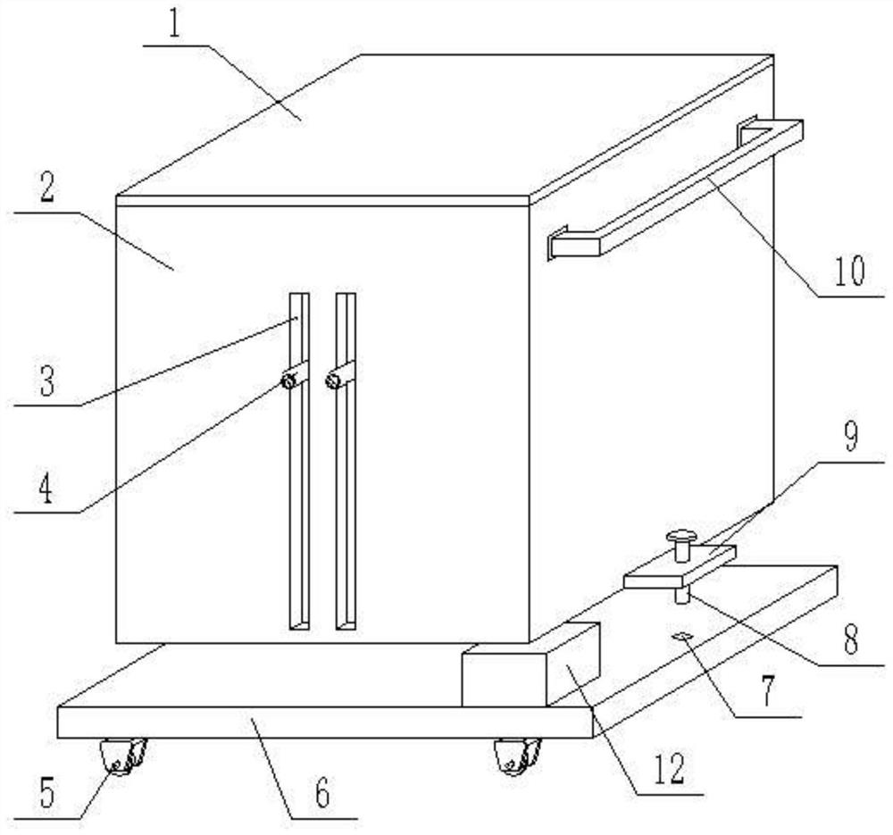
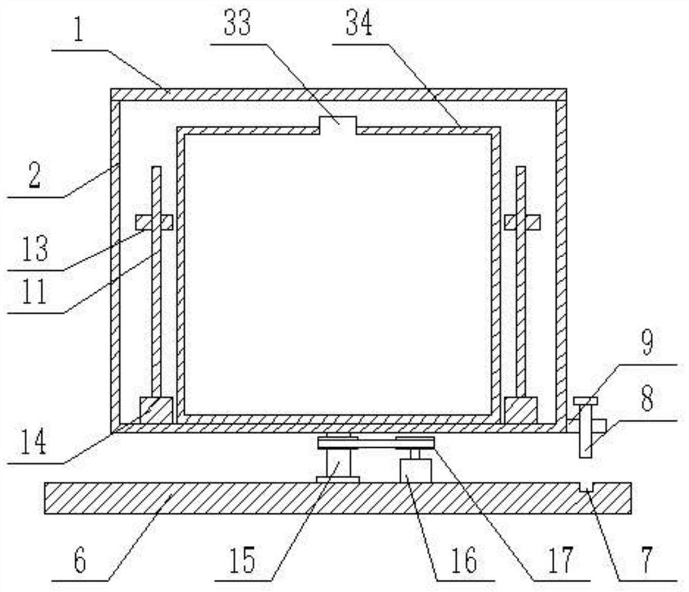
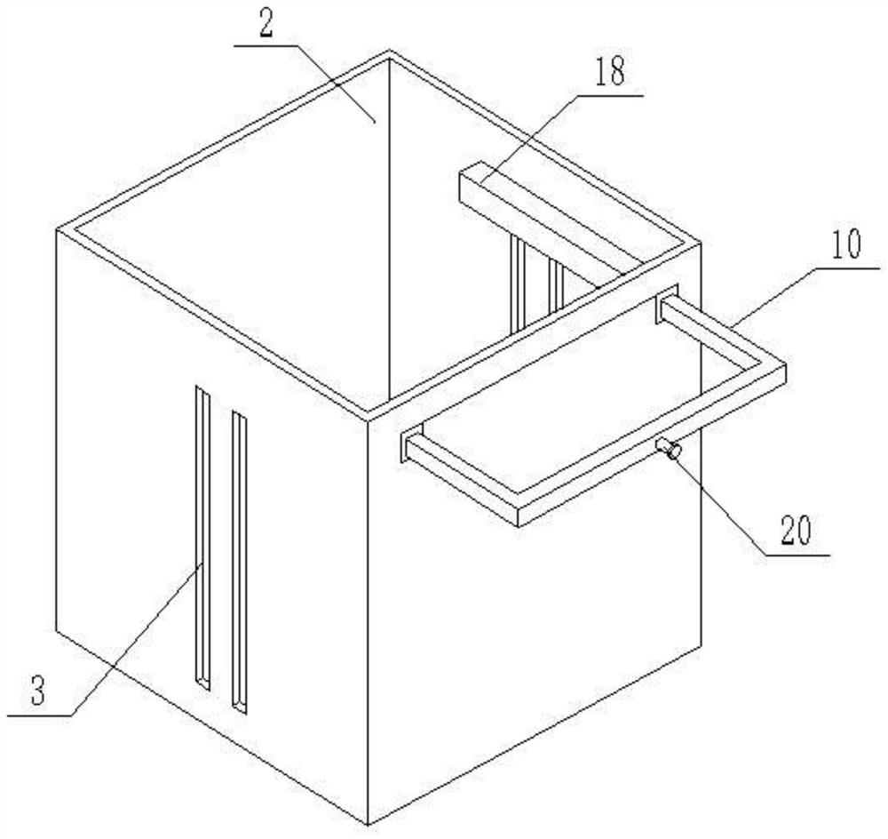
[0032] see Figure 1-8, a smoke treatment device for mine production, comprising a base 6, four universal wheels 5 are fixedly installed at the four corners of the lower end of the base 6, an electric control box 12 is fixedly installed on the upper end of the base 6, and a storage battery is arranged in the electric control box 12 and the controller, the upper end of the base 6 is provided with a housing 2, the upper end of the housing 2 is provided with an opening, the upper opening of the housing 2 is movably connected with the housing cover 1, and the middle part of the lower end of the housing 2 is fixedly connected with the rotating shaft 15, The lower end of the rotating shaft 15 is rotationally connected with the middle part of the upper surface of the base 6 through a bearing, and one side of the rotating shaft 15 is fixedly connected with a rotating motor 16 at the upper end of the base 6, and the input end of the rotating motor 16 is electrically connected to the output end of the electric control box 12. The output shaft of the rotating motor 16 and the rotating shaft 15 are fixedly connected with a rotating pulley 17, and the rotating pulley 17 on the output shaft of the rotating motor 16 and the rotating pulley 17 on the rotating shaft 15 pass through The drive belt is fixedly connected; the device can be moved by the universal wheel 5 at the lower end of the base 6, which is relatively convenient in the moving process. The output end of the electric control box 12 is connected with a rotating motor 16, and the storage battery in the electric control box 12 is the battery in the device. The electrical appliance supplies power, and the controller can control the rotating motor 16 to work. The rotating motor 16 drives the rotating shaft 15 to rotate through the rotating pulley 17 and the transmission belt, thereby driving the entire housing 2 to rotate;
[0033] One side of the lower end of the housing 2 is fixedly connected with a fixed plate 9, and the fixed plate 9 is threadedly connected with a bolt 8, and the lower end of the bolt 8 is provided with a socket 7 on the upper surface of the base 6, and a water tank is arranged on the inner side of the middle part of the housing 2. 34. The upper middle part of the water tank 34 is provided with a water injection hole 33, and the front and rear sides of the water tank 34 are provided with two water spray pipes 4, and the outer side of the water spray pipe 4 is provided with a through groove 3 on the outer wall of the housing 2. The water pipe 4 is connected to the water tank 34 through the connecting hose 15, a water pump is arranged at the connection between the connecting hose 15 and the water tank 34, the water pump is arranged in the water tank 34, and the input end of the water pump is electrically connected with the output end of the electric control box 12; Open the shell cover 1 and inject water into the water tank 34 through the water injection hole 33, and control the water pump to work by the electric control box 12. The water pump can spray the water in the water tank 34 through the connecting hose 15 and the water spray pipe 4;
[0034] The outside of the spray pipe 4 is provided with a lifting device, and the lifting device includes a mounting base 13, and the two ends of the mounting base 13 are provided with mounting holes 38, and the mounting holes 38 and the spraying pipe 4 are arranged in cooperation with each other. There is a chute 19, one end of the chute 19 is connected with the mounting hole 38, the other end of the chute 19 is fixedly connected with a stopper 44, the lower end of the water spray pipe 4 is fixedly connected with a slider 43, and the slider 43 is slidably set In the chute 19, the upper end of the mounting hole 38 is provided with a through hole on the mounting seat 13, and the through hole and the mounting hole 38 are connected to each other. In the sliding block 40, the middle part of the sliding block 40 is fixedly connected with a pull rod 36, and the upper end of the pull rod 36 is slidably connected with the middle part of the fixed block 39. There is a spring 41, the two ends of the spring 41 are fixedly connected with the fixed block 39 and the sliding block 40 respectively, the bottom of the pull rod 36 is fixedly connected with an arc-shaped clamping plate 37, and the upper end of the water spray pipe 4 is provided with an arc-shaped clamping groove 42. The clasp 37 and the arc-shaped draw-in groove 42 are set in cooperation with each other; when the water spray pipe 4 is installed, the water spray pipe 4 is slid into the chute 19 in the installation hole 38 through the slide block 43 at the lower end, and simultaneously upward Pull the pull rod 36, and the pull rod 36 drives the arc-shaped clamping plate 37 to move upward. When the slider 43 and the stopper 44 abut against each other, the arc-shaped clamping plate 37 and the arc-shaped clamping groove 42 overlap each other, and then the pull rod 36 is released , under the action of the elastic force of the spring 41, the spring 41 drives the sliding block 40 and the arc-shaped clamping plate 37 to move downward, and the arc-shaped clamping plate 37 and the arc-shaped clamping groove 42 are engaged with each other, so that the water spray pipe 4 is fixed ;
[0035] The two ends of mounting seat 13 are slidably connected with slide bar 35, and the lower end of slide bar 35 is fixedly connected with the bottom surface of housing 2, and the middle part of mounting seat 13 is threadedly connected with first threaded rod 11, and the lower end of first threaded rod 11 is fixed. A forward and reverse motor 14 is connected, the input end of the forward and reverse motor 14 is electrically connected with the output end of the electric control box 12, and the forward and reverse motor 14 is fixedly installed on the bottom surface of the housing 2; The reversing motor 14 rotates, and the forward and reverse motor 14 drives the first threaded rod 11 to rotate. The outer wall of the first threaded rod 11 is threadedly connected with the mounting seat 13, and the two sides of the mounting seat 13 are slidably connected with the slide bar 35. The rod 35 acts as a limiter, so that the mounting seat 13 can be raised and lowered. The lifting process drives the water spray pipe 4 to move up and down the through groove 3 on the housing 2, and the rotating motor 16 drives the housing 2 to rotate at the same time, so that the water tank The water within 34 is sprayed from all angles to reduce dust in the surrounding environment, and the coverage of water spray is greatly improved, and the above effects can be achieved without providing many nozzles;
[0036] The upper end of the housing 2 is provided with a pushing device, the pushing device includes a sleeve 18 and a U-shaped bar 10, the end of the U-shaped bar 10 is fixedly connected with a T-shaped connecting block 28, and the T-shaped connecting block 28 is slidably arranged in the sleeve 18 In the connecting groove 27 of the U-shaped rod 10, the inner middle part is arranged, and the outer middle part of the U-shaped rod 10 is provided with a rotating rod 20, and one end of the rotating rod 20 located on the inner side of the U-shaped rod 10 is fixedly connected with a first bevel gear 21, and the first bevel gear The lower end of the gear 21 is provided with a first connecting shaft 22, the first connecting shaft 22 is connected with a support plate 23 by bearing rotation, the support plate 23 is fixedly connected in the cavity of the U-shaped bar 10, the two ends of the first connecting shaft 22 and the middle part are all fixedly connected with the second bevel gear 24, and the second bevel gear 24 positioned at the first connecting shaft 22 middle part meshes with the first bevel gear 21, and the second bevel gear 24 on the first connecting shaft 22 both sides The second connecting shaft 25 is arranged on the side, and the upper end of the second connecting shaft 25 is connected to the top of the U-shaped bar 10 through bearings. The upper and lower ends of the second connecting shaft 25 are fixedly connected with the third bevel gear 26, which is located The third bevel gear 26 at the upper end of the shaft 25 meshes with the second bevel gear 24, and the third bevel gear 26 at the lower end of the second connection shaft 25 engages with the fourth bevel gear 30, and the middle part of the fourth bevel gear 30 is fixedly connected with the second bevel gear. Two threaded rods 29, the outer thread of the second threaded rod 29 is connected with a threaded pipe 31, the threaded pipe 31 is slidingly connected with the side wall of the U-shaped rod 10, the outer side wall section of the threaded pipe 31 is a rectangular structure, and on the inner wall of the sleeve pipe 18 A fixing hole 32 that cooperates with the threaded pipe 31 is provided; when the pushing device pusher needs to move, the U-shaped rod 10 is pulled out from the casing 18, and the fixing hole 32 and the threaded pipe 31 are aligned with each other at this time , by rotating the rotating rod 20 to drive the first bevel gear 21 to rotate, the first bevel gear 21 drives the second bevel gear 24 and the first connecting shaft 22 to rotate, and the first connecting shaft 22 drives the third bevel gear 26 through the second bevel gear 24 Rotate with the second connecting shaft 25, the third bevel gear 26 drives the fourth bevel gear 30 and the second threaded rod 29 to rotate, the outside of the second threaded rod 29 is threaded with the threaded pipe 31, the longitudinal section of the threaded pipe 31 is Rectangular structure and sliding connection with the side wall of the sleeve 18, so that the relative movement between the threaded pipe 31 and the second threaded rod 29 can occur, and then the threaded pipe 31 can be inserted into the fixing hole 32, thereby completing the entire U-shaped rod 10, now the pushing device can be moved by the pushing device.
[0037] Structural characteristics and working principle of the present invention: when the present invention is in use, the shell cover 1 can be opened to inject water into the water tank 34 through the water injection hole 33, and the water pump is controlled by the electric control box 12 to work, and the water pump can pass the water in the water tank 34 through Connect the hose 15 and the water spray pipe 4 to lead out for spraying. The electric control box 12 controls the forward and reverse motor 14 to rotate. The forward and reverse motor 14 drives the first threaded rod 11 to rotate. The outer wall of the first threaded rod 11 is connected to the The seat 13 is threaded, and the two sides of the mounting seat 13 are slidably connected with the sliding rod 35, and the sliding rod 35 acts as a limiter, so that the mounting seat 13 can be lifted, and the lifting process drives the water spray pipe 4 to pass through the housing 2 Groove 3 lifts, and controller can control rotating motor 16 to work, and rotating motor 16 drives rotating shaft 15 to rotate by rotating pulley 17 and transmission belt, thereby drives whole housing 2 to rotate, thereby makes the water in the water tank 34 flow from each Spray at an angle, reduce dust in the surrounding environment, greatly improve the coverage of water spray, and at the same time do not need to provide a lot of nozzles to achieve the above effects; when replacing and installing the water spray pipe 4, pass the water spray pipe 4 through the lower end The slider 43 slides into the chute 19 in the mounting hole 38, and pulls the pull rod 36 upwards at the same time, and the pull rod 36 drives the arc clamp 37 to move upward. When the slider 43 and the stopper 44 abut against each other, the arc The clamping plate 37 overlaps with the arc-shaped clamping groove 42, and then the pull bar 36 is released. Under the action of the elastic force of the spring 41, the spring 41 drives the sliding block 40 and the arc-shaped clamping plate 37 to move downward. The arc-shaped slots 42 are engaged with each other, so that the water spray pipe 4 is fixed; in addition, the bottom of the device is equipped with a universal wheel 5 and a pushing device. Pull out, at this moment the fixed hole 32 and the threaded pipe 31 are aligned with each other, the first bevel gear 21 is driven to rotate by rotating the rotating rod 20, the first bevel gear 21 drives the second bevel gear 24 and the first connecting shaft 22 to rotate, the first The connecting shaft 22 drives the third bevel gear 26 and the second connecting shaft 25 to rotate through the second bevel gear 24, and the third bevel gear 26 drives the fourth bevel gear 30 and the second threaded rod 29 to rotate, and the second threaded rod 29 The outer side is threadedly connected with the threaded pipe 31, and the longitudinal section of the threaded pipe 31 is a rectangular structure and is slidably connected with the side wall of the casing 18, so that the relative movement between the threaded pipe 31 and the second threaded rod 29 can be made, and then the threaded pipe 31 can be moved. The pipe 31 is inserted into the fixing hole 32, thereby completing the fixing of the whole U-shaped bar 10. At this time, the pushing device can be used to move. Before pushing, the housing 2 is rotated so that The bolt 8 is aligned with the insertion hole 7 on the base 6, and the bolt 8 is selected into the insertion hole 7, which can prevent the housing 2 from rotating during the process of pushing the device, and is easy to operate.
[0038] It will be apparent to those skilled in the art that the invention is not limited to the details of the above-described exemplary embodiments, but that the invention can be embodied in other specific forms without departing from the spirit or essential characteristics of the invention. Accordingly, the embodiments should be regarded in all points of view as exemplary and not restrictive, the scope of the invention being defined by the appended claims rather than the foregoing description, and it is therefore intended that the scope of the invention be defined by the appended claims rather than by the foregoing description. All changes within the meaning and range of equivalents of the elements are embraced in the present invention. Any reference sign in a claim should not be construed as limiting the claim concerned.
[0039] In addition, it should be understood that although this specification is described according to implementation modes, not each implementation mode only contains an independent technical solution, and this description in the specification is only for clarity, and those skilled in the art should take the specification as a whole , the technical solutions in the various embodiments can also be properly combined to form other implementations that can be understood by those skilled in the art.