Bidirectional bench clamp

A technology of clamp body and chute, which is applied in the direction of manufacturing tools, metal processing machinery parts, positioning devices, etc., can solve the problem that the clamping accuracy is difficult to meet the requirements of high symmetry and drilling processing, and achieves a strong universal effect

Active Publication Date: 2021-08-20
青岛海德锻造有限公司
View PDF7 Cites 0 Cited by
  • Summary
  • Abstract
  • Description
  • Claims
  • Application Information

AI Technical Summary

Problems solved by technology

[0003] The purpose of the present invention is to overcome the problem that the clamping accuracy of the existing vise is difficult to meet the drilling process of round or arc and square products with high symmetry requirements, and to provide a two-way vise, through the slide plate and positioning The plate converts the reciprocating action of the linear reciprocating mechanism into the common advance and common retreat of the left slider and the right slider, and realizes the bidirectional clamping and loosening of the workpiece

Method used


Image

  • Bidirectional bench clamp
  • Bidirectional bench clamp
  • Bidirectional bench clamp

Examples


Embodiment 1

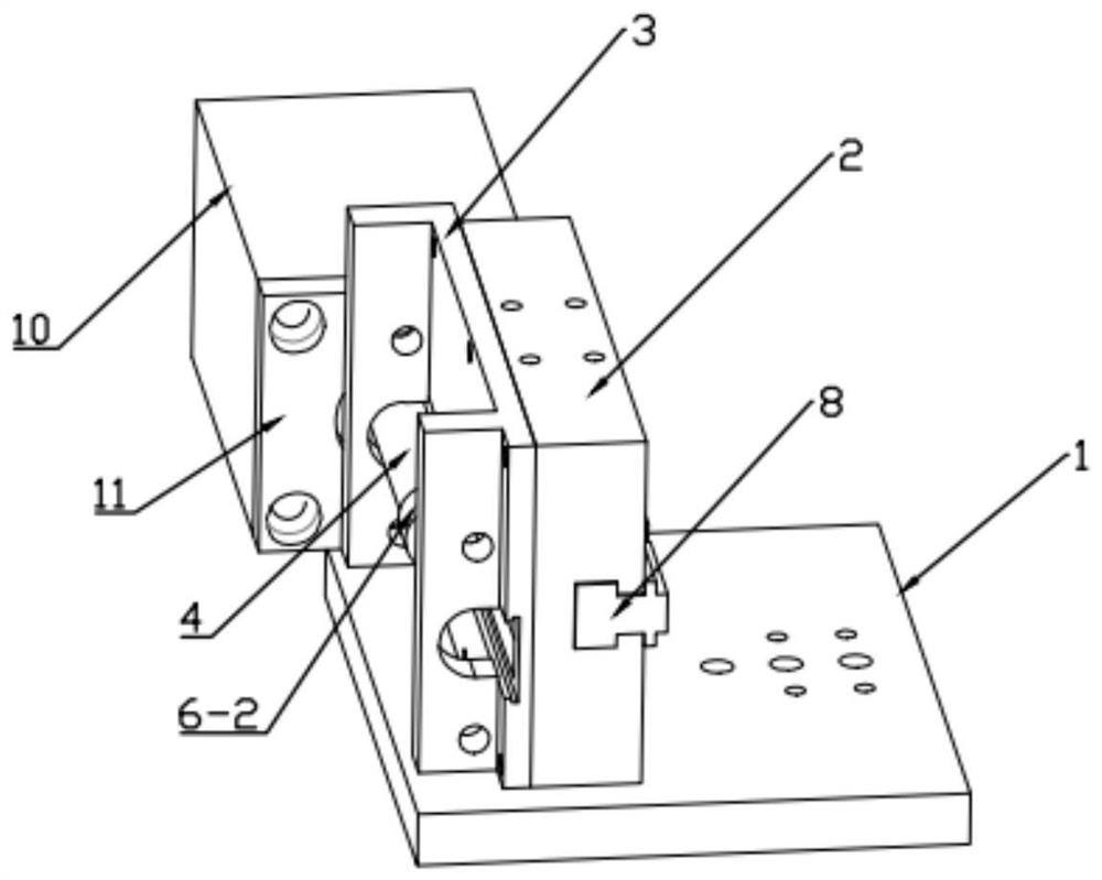
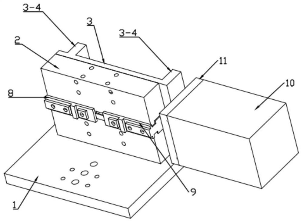
[0032] A two-way vise comprises a bottom plate 1, a pliers body 2, a bracket 3, a spacer 4, a pull rod 5, a slide plate 6, a positioning plate 7, a left slider 8, a right slider 9 and a linear reciprocating mechanism 10.

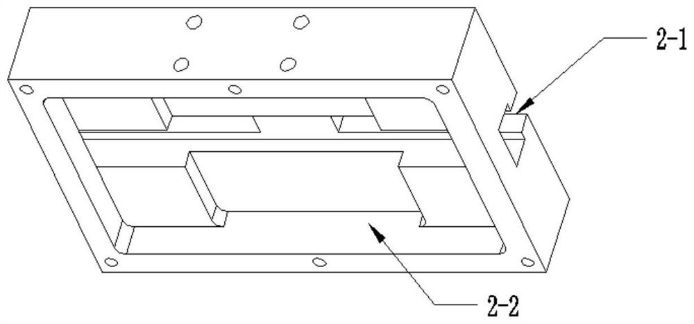
[0033] Such as image 3 and Figure 4 As shown, the front end surface of the pliers body 2 is horizontally provided with a first chute 2-1, and the rear end surface is provided with an installation groove 2-2, and the first chute 2-1 communicates with the installation groove 2-2.

[0034] Such as figure 2 and 5 and Figure 6 As shown, the left slider 8 and the right slider 9 are symmetrical, the front end faces of the left slider 8 and the right slider 9 are provided with jaw mounting parts for installing different jaws, and the rear end faces are provided with projections.

[0035] Such as Figure 7 and Figure 8 As shown, the front end surface of the positioning plate 7 is provided with two second chute 7-1 and 7-2, the second chute 7-1 and 7-2 are ...

Embodiment 2

[0042] Such as Figure 16 As mentioned above, the jaws are installed on the left slider and the right slider according to the positions shown by the arrows. The two-way vise can support and fix different types of workpieces by changing different jaws. Such as Figure 17 As shown, by changing different jaws, the two-way vise can respectively fix two different workpieces, the ear ring and the ear fork. When using the bidirectional vise of the present invention to process different workpieces, only the matching jaws need to be replaced. Therefore, the bidirectional vise of the present invention has strong versatility.


PUM


Abstract

The invention relates to the technical field of clamps. In order to solve the problem that the clamping precision of an existing bench clamp cannot meet the requirement for machining of round or circular arc and square products with the high symmetry degree requirement, the invention provides a bidirectional bench clamp. A clamp body and a support are fixedly arranged on a base, the support is fixedly arranged on the rear end face of the clamp body, a left sliding block and a right sliding block are symmetrically arranged on a first sliding groove, a positioning plate is arranged in an installation groove between the clamp body and the support, protruding blocks on the left sliding block and the right sliding block are arranged in two second sliding grooves of the positioning plate respectively, the protruding blocks of the positioning plate are arranged in a third sliding groove in a sliding plate, the protruding part of the sliding plate penetrates out of a fourth sliding groove, a spacer bush is fixedly arranged on the protruding part, one end of a pull rod is fixedly connected with the spacer bush, and the other end is fixedly connected with a telescopic shaft of a linear reciprocating mechanism. According to the bidirectional bench clamp, the reciprocating action of the linear reciprocating mechanism is converted into co-advancing and co-retreating actions of the left sliding block and the right sliding block through the sliding plate and the positioning plate, and bidirectional clamping and loosening of a workpiece are achieved.

Description

technical field [0001] The invention relates to the technical field of clamps, in particular to a bidirectional vise. Background technique [0002] In today's mechanical processing field, people usually use a vise to fix the workpiece effectively and stably. The common vise mainly includes a fixed vise seat and a movable vise seat, and the workpiece is located between the fixed vise seat and the movable vise seat. In the jaws between the movable jaws, the movable jaw moves towards the fixed jaws through the rotation of the rotating drive rod, so that the workpiece is clamped between the fixed jaws and the movable jaws. After the workpiece is tightened and fixed in this way can be processed. This vise is simple in structure and easy to use, and is widely used in the field of machining. However, this type of vise also has certain defects, such as: it cannot meet the drilling processing of circular or arc and square products with high symmetry requirements; the versatility is...

Claims


Application Information

Patent Timeline
Patent Type & Authority Applications(China)
IPC IPC(8): B23Q3/06
CPCB23Q3/066
Inventor 周德
Owner 青岛海德锻造有限公司
Why Eureka
Try Eureka