
Machining equipment for equipment part production

A technology for processing equipment and parts, which is applied in the field of processing equipment for the production of equipment parts, and can solve problems such as manual flipping of workpieces

Active Publication Date: 2022-07-29
佛山市景丰号机械配件有限公司
View PDF5 Cites 0 Cited by
  • Summary
  • Abstract
  • Description
  • Claims
  • Application Information

AI Technical Summary

Problems solved by technology

[0004] The invention provides a processing equipment for the production of equipment parts, which solves the technical problem in the related art that a single-axis drilling machine needs to manually turn over the workpiece when the workpiece is processed on multiple surfaces.

Method used


Image

  • Machining equipment for equipment part production
  • Machining equipment for equipment part production
  • Machining equipment for equipment part production

Examples


Embodiment 1

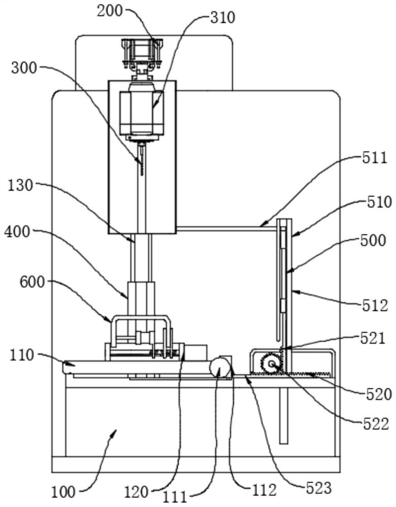
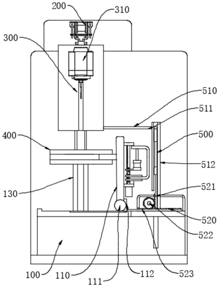
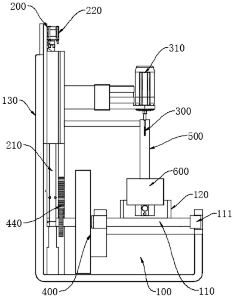
[0036] like Figure 1-Figure 11 As shown, a processing equipment for the production of equipment parts includes a worktable 100 and a fixture 120, the upper table surface of the worktable 100 is horizontal, and a turning table 110 is installed, and the fixture 120 clamps the workpiece 600 to the upper table surface of the turning table 110, The workpiece 600 has a U-shaped structure,

[0037] It also includes a lifting assembly 200, a drill bit 300, a turning assembly 400 and an adjusting assembly 500. The drilling head 300 is arranged above the worktable 100 and corresponds to the position of the workpiece 600. The lifting assembly 200 is used to drive the drilling head 300 to rise and fall, and the turning assembly 400 is connected to the lifting assembly. 200 is matched to drive the turning assembly 400 to drive the turning table 110 to turn from the horizontal state to the vertical state by ninety degrees during the ascending process. The turning table 110 moves horizonta...


PUM


Abstract

The invention relates to the field of part machining, in particular to machining equipment for equipment part production, which comprises a workbench, a clamp, a lifting assembly, a drill bit, an overturning assembly and an adjusting assembly, the upper table surface of the workbench is horizontal and is provided with an overturning table, and the machining equipment further comprises the lifting assembly, the drill bit, the overturning assembly and the adjusting assembly. The lifting assembly is used for driving a drill bit to ascend and descend, the overturning assembly is matched with the lifting assembly and used for driving the overturning assembly to drive the overturning table to be overturned by 90 degrees from the horizontal state to the vertical state in the ascending process, and the adjusting assembly is matched with the lifting assembly. After the workpiece is installed on the overturning table, a drill bit descends for the first time to drill one side face of the workpiece, the overturning table is driven to overturn in the ascending process, the other side face of the workpiece corresponds to the drill bit, and then the drill bit descends for the second time to drill the other side face of the workpiece. And then drilling machining of different side faces of the workpiece can be achieved through a single-shaft drilling machine.

Description

technical field [0001] The invention relates to the field of parts processing, more particularly, to a processing equipment for producing equipment parts. Background technique [0002] Drilling machine refers to a machine tool that mainly uses a drill to machine holes in a workpiece. Usually the rotation of the drill bit is the main movement, and the axial movement of the drill bit is the feed movement. The drilling machine has a simple structure and relatively low machining accuracy. It can drill through holes and blind holes, replace special tools, and can expand, countersink, ream or tap. During the machining process, the workpiece does not move, the tool is moved, the center of the tool is aligned with the center of the hole, and the tool is rotated (main motion). The feature of the drilling machine is that the workpiece is fixed and the tool rotates. [0003] The drilling machine is divided into single-axis and multi-axis. When the workpiece is processed on multiple ...

Claims


Application Information

Patent Timeline
Patent Type & Authority Applications(China)
IPC IPC(8): B23Q3/06B23Q1/25B23Q1/44
CPCB23Q3/06B23Q1/25B23Q1/44Y02P70/10
Inventor 魏然
Owner 佛山市景丰号机械配件有限公司
Learn More