Numerical control machine tool automatic wiring device

A technology of automatic wiring and CNC machine tools, which is applied in the direction of positioning devices, feeding devices, metal processing machinery parts, etc., and can solve problems such as weakening of the sealing effect, wiring, and difficult inner walls of pipe fittings

Pending Publication Date: 2019-07-26
海力士五金机电(昆山)有限公司
View PDF0 Cites 0 Cited by
  • Summary
  • Abstract
  • Description
  • Claims
  • Application Information

AI Technical Summary

Problems solved by technology

[0003] One of the methods of making electrofusion pipe fittings is to wire the inner wall of the pipe fitting. This wiring requires the enameled wire to stay on the inner wall of the pipe fitting and not allow it to fall off, because once it falls off, it is difficult to rewire the inner wall of the pipe fitting. Uneven wiring of enameled wires will greatly weaken the effect of sealing and bonding

Method used


Image

  • Numerical control machine tool automatic wiring device
  • Numerical control machine tool automatic wiring device
  • Numerical control machine tool automatic wiring device

Examples


Embodiment Construction

[0021] The present invention will be further described below in conjunction with specific drawings.

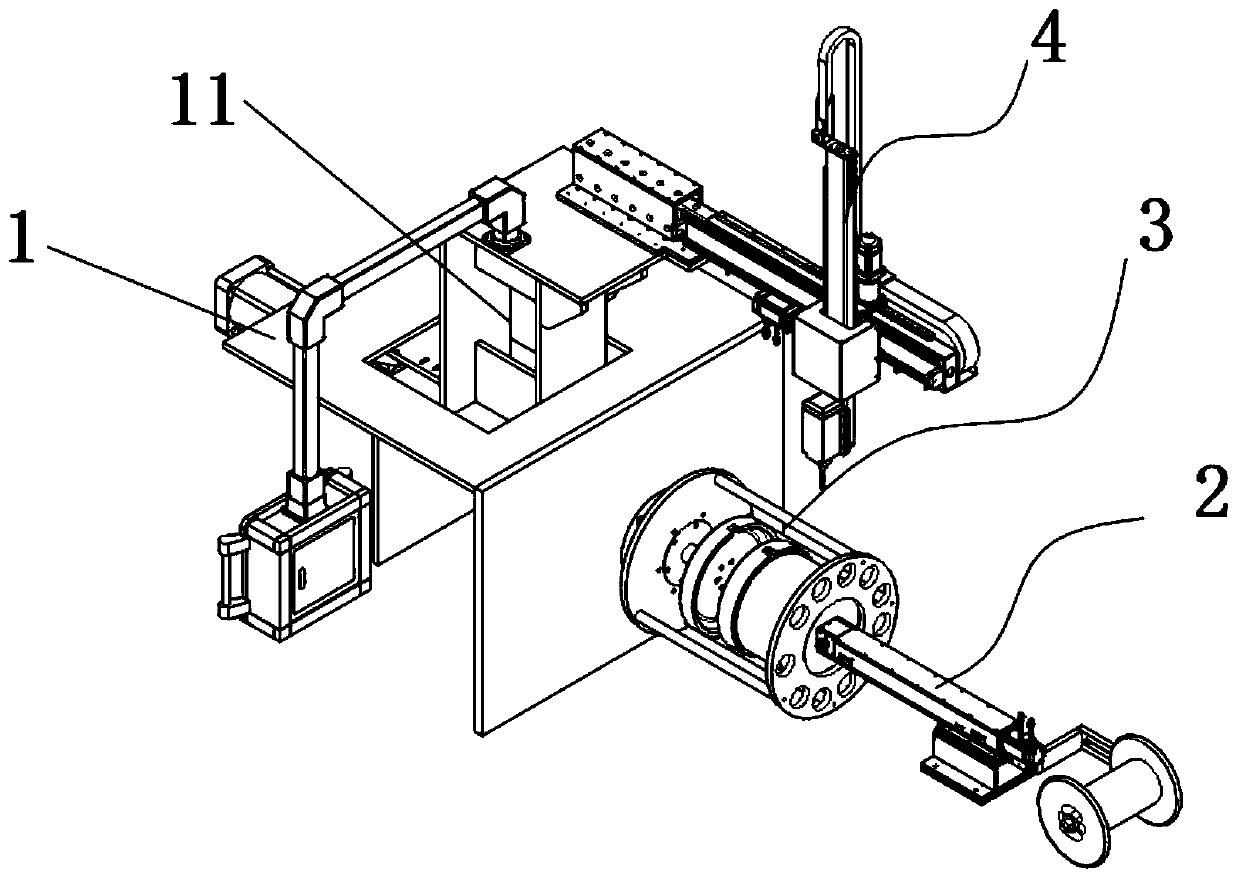
[0022] like figure 1 As shown, a CNC machine tool automatic wiring device is provided, including a CNC machine body 1, a tool rest module 2 arranged on the body 1, a clamp module 3 connected to the tool rest module 2, and gears are arranged in the body 1 The box 11 and the gear box 11 are externally connected with a drilling module 4 .

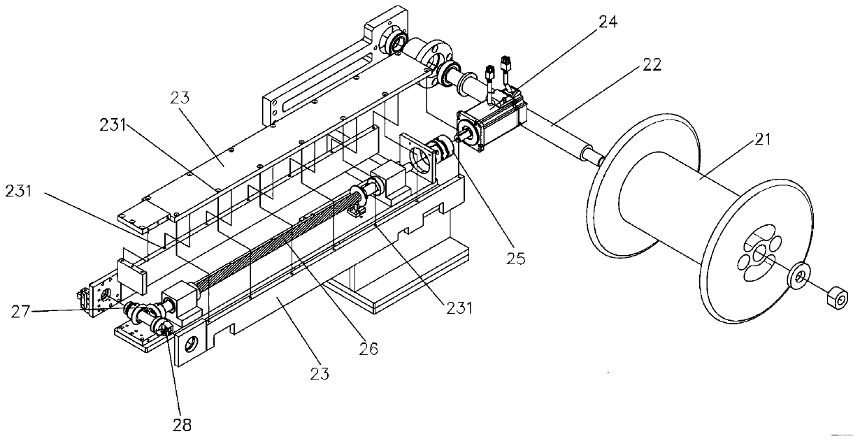
[0023] like figure 2 As shown, wherein: the tool post module 2 includes a wire wheel 21, the wire wheel 21 is I-shaped, the wire wheel shaft 22, and the wire wheel 21 is arranged on the wire wheel shaft 22; the connecting bracket 23 is set on the connecting bracket 23 There are a plurality of threading holes 231; the servo motor 24, the shaft coupling 25 connected with the servo motor 24, the gear shaft 26 connected with the shaft coupling 25, and a pair of bevel gears 27 are arranged at the output end of the gear shaft 26, the one A cutte...


PUM


Abstract

The invention discloses a numerical control machine tool automatic wiring device comprising a machine body (1), a tool rest module (2) arranged on the machine body (1), a clamp module (3) connected with the tool rest module (2), a gear box (11) arranged in the machine body (1), and a hole drilling module (4) externally connected to the gear box (11). According to the numerical control machine toolautomatic wiring device, a pipe fitting to be subjected to wiring is clamped on the clamp module, a servo motor in the tool rest module drives tool bits to move, and an enameled wire is driven by thetool bits to conduct reciprocating automatic wiring on the inner wall of the pipe fitting; and meanwhile the hole drilling module can conduct hole drilling machining on the pipe fitting. Due to the adoption of the numerical control machine tool automatic wiring device, double-layer or multi-layer wiring can be conducted on the inner wall of the pipe fitting, and hole drilling machining can be further conducted on the pipe fitting synchronously through the hole drilling module.

Description

technical field [0001] The invention relates to the field of pipe fitting wiring, in particular to an automatic wiring device for a numerically controlled machine tool. Background technique [0002] Electrofusion fittings are heated by the Joule effect by heating elements embedded in the interface between it and the pipe, causing the material around them to melt, thereby fusing the pipe and fitting surfaces together. [0003] One of the methods of making electrofusion pipe fittings is to wire the inner wall of the pipe fitting. This wiring requires the enameled wire to remain on the inner wall of the pipe fitting and not allowed to fall off, because once it falls off, it is difficult to rewire the inner wall of the pipe fitting, and if the inside of the spiral coil pipe fitting If the enameled wire is unevenly routed, the effect of sealing and bonding will be greatly weakened. For the inner wall of pipe fittings that require double-layer or multi-layer wiring, how to realiz...

Claims


Application Information

Patent Timeline
Patent Type & Authority Applications(China)
IPC IPC(8): B23P23/04B23Q3/08B23Q5/28
CPCB23P23/04B23Q3/08B23Q5/28
Inventor 韩佳佳
Owner 海力士五金机电(昆山)有限公司
Why Eureka
Try Eureka