In-pipeline working body transporting and positioning device, transporting method and positioning method

A technology for positioning devices and working bodies, which is applied in the direction of special pipes, pipe components, pipes/pipe joints/pipe fittings, etc., and can solve problems that are difficult to achieve

Active Publication Date: 2019-12-24
XIAN UNIV OF TECH
View PDF15 Cites 0 Cited by
  • Summary
  • Abstract
  • Description
  • Claims
  • Application Information

AI Technical Summary

Problems solved by technology

[0003] It is mainly manifested in two aspects, one is how to send the processing or repairing device into the pipeline, and the other is how to obtain the specific position of the processing or repairing device after entering the pipeline, and how to realize the positioning; the above two aspects are currently very difficult. Difficult to achieve

Method used


Image

  • In-pipeline working body transporting and positioning device, transporting method and positioning method
  • In-pipeline working body transporting and positioning device, transporting method and positioning method
  • In-pipeline working body transporting and positioning device, transporting method and positioning method

Examples


Embodiment 2

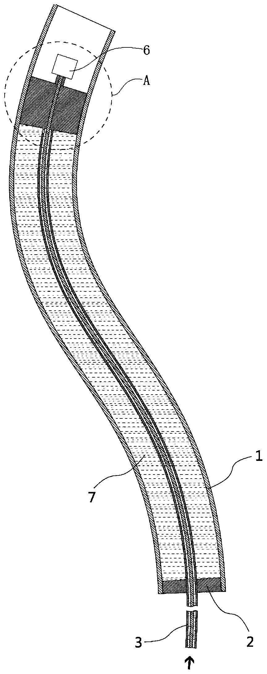
[0057] The working body 6 is a camera; when the inner wall of the pipeline 1 needs to be overhauled, the working body 6 is replaced with a camera with a light, and the camera can take pictures and videos of the inner wall of the pipeline 1 to know the situation of the inner wall of the pipeline 1.

[0058] The working body 6 is a drilling device; when drilling operations need to be performed on the inner wall of the pipeline 1, the working body 6 can be replaced with a common drilling device with a drill bit.

[0059] The working body 6 is a cutting and finishing device for the inner wall of the pipeline; the cutting and finishing device for the inner wall of the pipeline can uniformly cut and finish the inner wall of the curved pipeline 1 .

[0060] It should be noted that the working body 6 is not limited to the above-mentioned several embodiments, and can also be any device for performing other operations on the pipeline 1 .

[0061] It should be noted that if the drilling ...

Embodiment 3

[0081] A method for transporting a working body in a pipeline, using the positioning device for transporting a working body in a pipeline according to Embodiment 1, comprising the following specific steps:

[0082] Step 1: Measure the inner diameter of the pipe; first use an inner diameter measuring device such as a vernier caliper to measure the inner diameter of the pipe, and skip this step if the inner diameter is known.

[0083] Step 2: Initialize the working state; select the corresponding first rubber plug 2 and second rubber plug 5 according to the inner diameter of the pipe, and then empty the inside of the flexible pipe 3. If there is hydraulic oil remaining in the flexible pipe 3, use a hydraulic pump to evacuate it ; or blowing high-speed airflow into the flexible pipe 3 to discharge the hydraulic oil in the flexible pipe 3, and then connect the working body in the pipeline 1 to transport the positioning device. Then put the tail of the second rubber plug 5 close to...

Embodiment 4

[0087] A method for positioning a working body in a pipeline, based on the positioning of the working body in the pipeline during transportation,

[0088] Step A: Measure the distance l traveled by the flexible pipe 3 1 ; With the initial state in step 2 as the starting point of the flexible pipe 3, straighten the flexible pipe 3 outside the pipeline 1, and look for a reference point on the flexible pipe 3, such as the position where the flowmeter is installed, when the flexible pipe 3 is When the second rubber stopper 5 advances to the inside of the pipe 1, measure the distance advanced by the reference point to obtain the distance l traveled by the flexible pipe 3 1 .

[0089] Step B: Calculate the volume of hydraulic oil in pipeline 1. The flowmeter can measure the total amount of hydraulic oil flowing through. The distance between the installation position of the flowmeter and the joint between the flexible pipe 3 and the second rubber plug 5 is known when the flowmeter ...


PUM


Abstract

The invention discloses an in-pipeline working body transporting and positioning device, a transporting method and a positioning method. The in-pipeline working body transporting and positioning device comprises a first rubber stopper, a flexible pipe and a second rubber stopper. One end of the flexible pipe penetrates through the first rubber stopper and the second rubber stopper to be connectedwith a working body, and the other end of the flexible pipe is connected with a hydraulic pump. The outer wall of the part, between the first rubber stopper and the second rubber stopper, of the flexible pipe is provided with a pipe wall hole. A device for pipeline machining or overhauling can be fed into a pipeline. The working body can be successfully transported into the pipeline, drilling machining, overhauling, finishing and the like can be carried out in the pipeline, and the in-pipeline working body transporting and positioning device, the transporting method and the positioning methodare suitable for various types of straight pipes and elbow pipes.

Description

technical field [0001] The invention belongs to the technical field of pipeline finishing, and relates to a transport and positioning device for a working body in a pipeline, and also relates to a transport method for a working body in a pipeline, and a positioning method for a transport and positioning device for a working body in a pipeline. Background technique [0002] Pipes are common parts in production and life, including straight pipes and bent pipes. Due to the poor openness of the pipeline, it is very difficult to perform operations such as drilling, repairing, and finishing on the inner wall of the pipeline. For example, it is necessary to drill holes at specific positions inside the pipeline, or install sensors, or inspect the damage location inside the pipeline. This is still the case for straight pipes, but it is even more difficult to realize the above operations for bent pipes. [0003] It is mainly manifested in two aspects, one is how to send the processin...

Claims


Application Information

Patent Timeline
Patent Type & Authority Applications(China)
IPC IPC(8): F16L55/38F16L101/10
CPCF16L55/38F16L2101/10
Inventor 淮文博
Owner XIAN UNIV OF TECH
Why Eureka
Try Eureka