
Exhaust fan with fan blades convenient to clean

An exhaust fan and cleaning technology, which is applied to the components of the pumping device for elastic fluids, mechanical equipment, machines/engines, etc., can solve the problem of inconvenient adjustment, the adjustment leaf does not have a cleaning cotton structure, and it is inconvenient to adjust the leaf dust. cleaning, etc.

Active Publication Date: 2021-08-20
南通安泰风机有限公司
View PDF10 Cites 0 Cited by
  • Summary
  • Abstract
  • Description
  • Claims
  • Application Information

AI Technical Summary

Problems solved by technology

[0004] The purpose of the present invention is to provide an exhaust fan that is easy to clean the fan blades, which solves the problem that when the existing exhaust fans are in use, a large amount of dust is easy to accumulate on the fan blades after a long period of use, which reduces the work of the exhaust fan. efficiency, it is inconvenient to clean the fan blades; when the existing exhaust fan is in use, due to the limitation of environmental conditions, the direction of the air outlet of the exhaust fan needs to be adjusted when the exhaust fan is in use. It is inconvenient to adjust the direction of the tuyere; when the existing exhaust fan is in use, it is inconvenient to clean the dust on the adjustment blade, and the adjustment blade itself does not have the technical problem of cleaning cotton structure

Method used


Image

  • Exhaust fan with fan blades convenient to clean
  • Exhaust fan with fan blades convenient to clean
  • Exhaust fan with fan blades convenient to clean

Examples


Embodiment Construction

[0028] The technical solutions of the present invention will be clearly and completely described below in conjunction with the embodiments. Apparently, the described embodiments are only some of the embodiments of the present invention, not all of them. Based on the embodiments of the present invention, all other embodiments obtained by persons of ordinary skill in the art without creative efforts fall within the protection scope of the present invention.

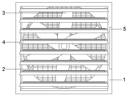
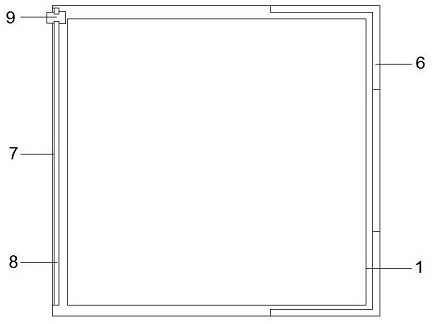
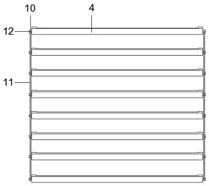
[0029] see Figure 1-7 As shown, an exhaust fan that is convenient for cleaning blades includes an exhaust fan box 1, a protective net 2 is installed on the back of the exhaust fan box 1 near the middle, an exhaust fan 3 is installed on the inside of the exhaust fan box 1 near the middle, and the back side of the exhaust fan 3 A motor connected to the exhaust box 1 is installed in the middle, and eight regulating leaves 4 are installed on the front of the exhaust box 1, and each of them runs through the inside of the exhaus...


PUM


Abstract

The invention discloses an exhaust fan with fan blades convenient to clean. The exhaust fan comprises an exhaust fan box, wherein a protective net is installed at the position, close to the middle, of the back face of the exhaust fan box, an exhaust fan is installed at the position, close to the middle, of the interior of the exhaust fan box, and a motor connected with the exhaust fan box is installed at the position, close to the middle, of the back face of the exhaust fan; eight adjusting blades penetrating through the inner side of the exhaust fan box are installed on the front face of the exhaust fan box, a side groove penetrating through the side face, the top face, the bottom face and the front face of the exhaust fan box is formed in the position, close to the front end, of one side of the exhaust fan box, a blade clamping mechanism is installed in the side groove, and a sliding groove is formed in the position, close to the other side, of the interior of the exhaust fan box; and a fastening plate is mounted on one side of the sliding groove. The exhaust fan has the good capability of promoting air flow, can conveniently clean the fan blades of the exhaust fan, can conveniently clean dust on the adjusting blades, can adjust the wind direction of the exhaust fan, and can adapt to different environments.

Description

technical field [0001] The invention relates to the field of exhaust fans, in particular to an exhaust fan which is convenient for cleaning fan blades. Background technique [0002] Exhaust fans can bring fresh air to people. Fresh and smooth air brings a feeling of refreshment and invigoration, while stagnant and hot air can make people listless and drowsy. The flow of air around the human body can Promote the evaporation of body fluids, and the exhaust fan plays a role in natural cooling, thereby avoiding discomfort caused by poor ventilation such as stuffy heat, peculiar smell, dust, and oily smoke. [0003] Existing exhaust fans have certain disadvantages in use. When the existing exhaust fans are in use, after a long period of use, a large amount of dust is easy to accumulate on the fan blades, which reduces the working efficiency of the exhaust fans and is inconvenient to use. The fan blades are cleaned; when the existing exhaust fan is in use, due to the limitation o...

Claims


Application Information

Patent Timeline
IPC IPC(8): F04D25/14F04D29/70F04D29/64
CPCF04D25/14F04D29/646F04D29/703
Inventor 王枨
Owner 南通安泰风机有限公司
Learn More