
Hydraulic transmission

A transmission and hydraulic technology, applied in the field of hydraulic transmission, can solve the problems of heavy transmission gearbox, unoptimized high speed and high energy consumption, and not well balanced.

Pending Publication Date: 2021-08-20
王世峰
View PDF0 Cites 0 Cited by
  • Summary
  • Abstract
  • Description
  • Claims
  • Application Information

AI Technical Summary

Problems solved by technology

[0002] Because the transmission gearbox is too bulky for electric vehicles, most of them give up the gearbox and adopt single-stage transmission, which can only achieve high power output through high speed
However, the characteristics of low-speed and high-torque motors have not been fully utilized, and the characteristics of high-speed and high energy consumption have not been optimized. The two have not been well balanced, resulting in waste of some energy

Method used


Image

  • Hydraulic transmission
  • Hydraulic transmission
  • Hydraulic transmission

Examples


Embodiment Construction

[0022] Embodiments of the technical solutions of the present invention will be described in detail below in conjunction with the accompanying drawings. The following examples are only used to illustrate the technical solutions of the present invention more clearly, and therefore are only examples, rather than limiting the protection scope of the present invention.

[0023] It should be noted that, unless otherwise specified, the technical terms or scientific terms used in this application shall have the usual meanings understood by those skilled in the art to which the present invention belongs.

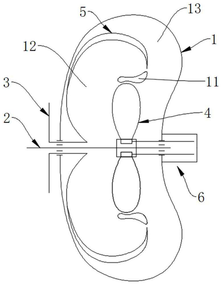
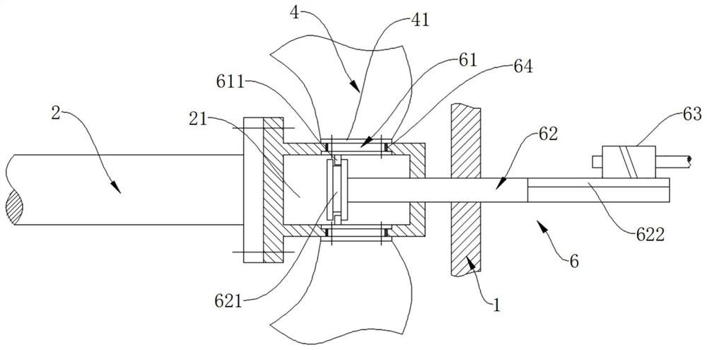
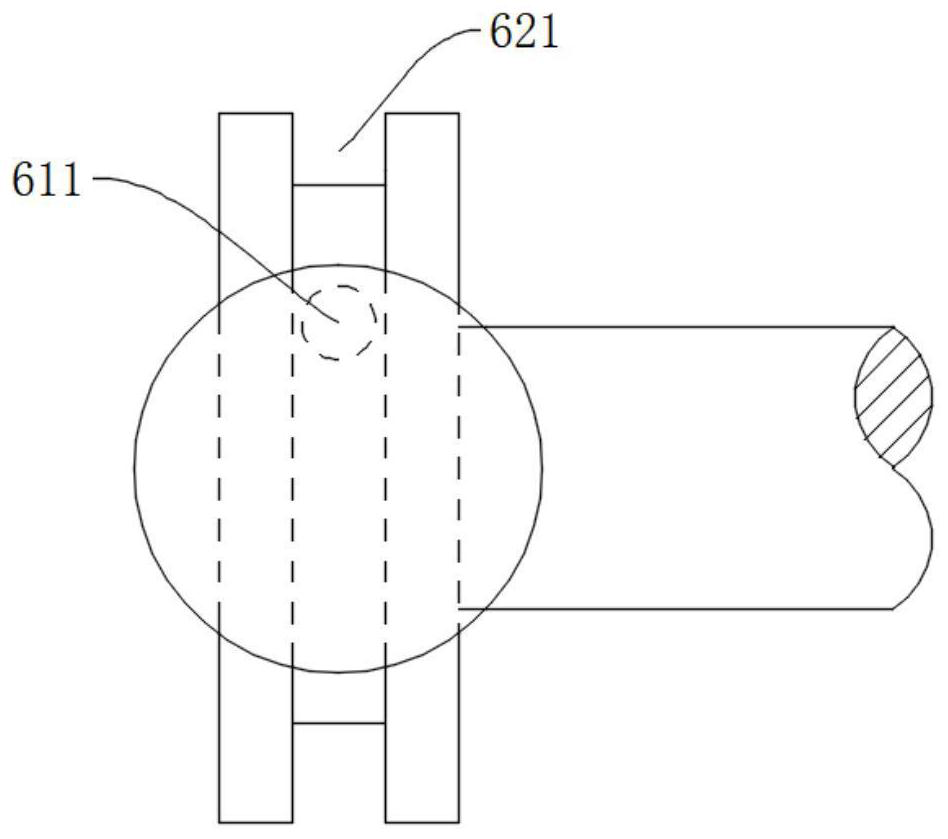
[0024] Such as figure 1 , figure 2 , image 3 , Figure 4 , Figure 5 , Image 6 with Figure 7 As shown, this embodiment provides a hydraulic transmission, including a housing 1, the housing 1 is integrally cast with a flow guide 11, and the housing 1 is filled with hydraulic fluid; it also includes concentric different Shaft arrangement of input shaft 2 and output shaft 3. ...


PUM

PropertyMeasurementUnit
Rotation angleaaaaaaaaaa

Abstract

The invention relates to a hydraulic transmission which comprises a shell, an input shaft, and an output shaft. A flow guide piece is fixedly arranged in the shell, and the shell is filled with oil. The input shaft comprises a first input section located on the outer side of the shell and a second input section located in the shell, and a plurality of blades are evenly distributed on the outer circumference of the second input section. The output shaft and the input shaft are concentrically and non-coaxially arranged, the output shaft comprises a first output section located on the outer side of the shell and a second output section located in the shell, and the outer periphery of the second output section is fixedly sleeved with a centrifugal impeller. A centrifugal cavity is formed in the shell, and the oil in the centrifugal cavity flows in two directions in the radial direction of the centrifugal impeller. The blades are installed on the input shaft through installation bases, the installation bases are connected with an angle adjusting mechanism, and the angle adjusting mechanism can drive the installation bases to rotate around the axes of the installation bases. The rotating direction and the rotating speed of the output shaft can be changed by changing the angles of the blades, and stepless speed regulation of the transmission is achieved.

Description

technical field [0001] The invention relates to the technical field of transmissions, in particular to a hydraulic transmission. Background technique [0002] Because the transmission gearbox of electric vehicles is too bulky, most of them give up the gearbox and adopt single-stage transmission, which can only achieve high power output through high speed. However, the characteristics of low-speed and high-torque motors have not been fully utilized, and the characteristics of high-speed and high energy consumption have not been optimized. The two have not been well balanced, resulting in a waste of energy. Contents of the invention [0003] Aiming at the defects in the prior art, the technical problem to be solved by the present invention is to provide a hydraulic transmission, which can realize the transmission effect by adjusting the installation angle of the blades on the input shaft and using the hydraulic fluid as the power transmission carrier. [0004] In order to s...

Claims


Application Information

Patent Timeline
IPC IPC(8): F16D33/04F16D33/20F16D33/18
CPCF16D33/04F16D33/18F16D33/20
Inventor 王世峰王睿宁
Owner 王世峰
Learn More