Automatic separation device for roof tiles
An automatic separation and tile technology, applied in auxiliary molding equipment, ceramic molding machines, manufacturing tools, etc., can solve problems such as increasing people's fatigue, delaying factory production, and affecting tile separation progress
- Summary
- Abstract
- Description
- Claims
- Application Information
AI Technical Summary
Problems solved by technology
Method used
Image
Examples
Embodiment 1
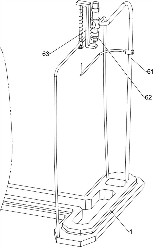
[0083] An automatic separation device for roof tiles, such as figure 1 As shown, it includes a base 1, a pillar 2, a guide rail 3, a clamping mechanism 4, a separation mechanism 5 and a reciprocating mechanism 6. The left and right sides of the base 1 are symmetrically provided with pillars 2, and the upper sides of the inner walls of the pillars 2 on the front and rear sides Guide rails 3 are arranged between them, clamping mechanism 4 is arranged between the guide rails 3 on both sides, separation mechanism 5 is arranged on the left side on the base 1, and reciprocating mechanism 6 is arranged between the left front side on the base 1 and the top of separation mechanism 5 .
[0084] When people need to separate the roof tiles, they can use the automatic separation and transposition of the roof tiles. At first people need to pull the clamping mechanism 4 to move backwards, and then put the tiles into the clamping mechanism 4. After people let go, the clamping mechanism 4 will...
Embodiment 2
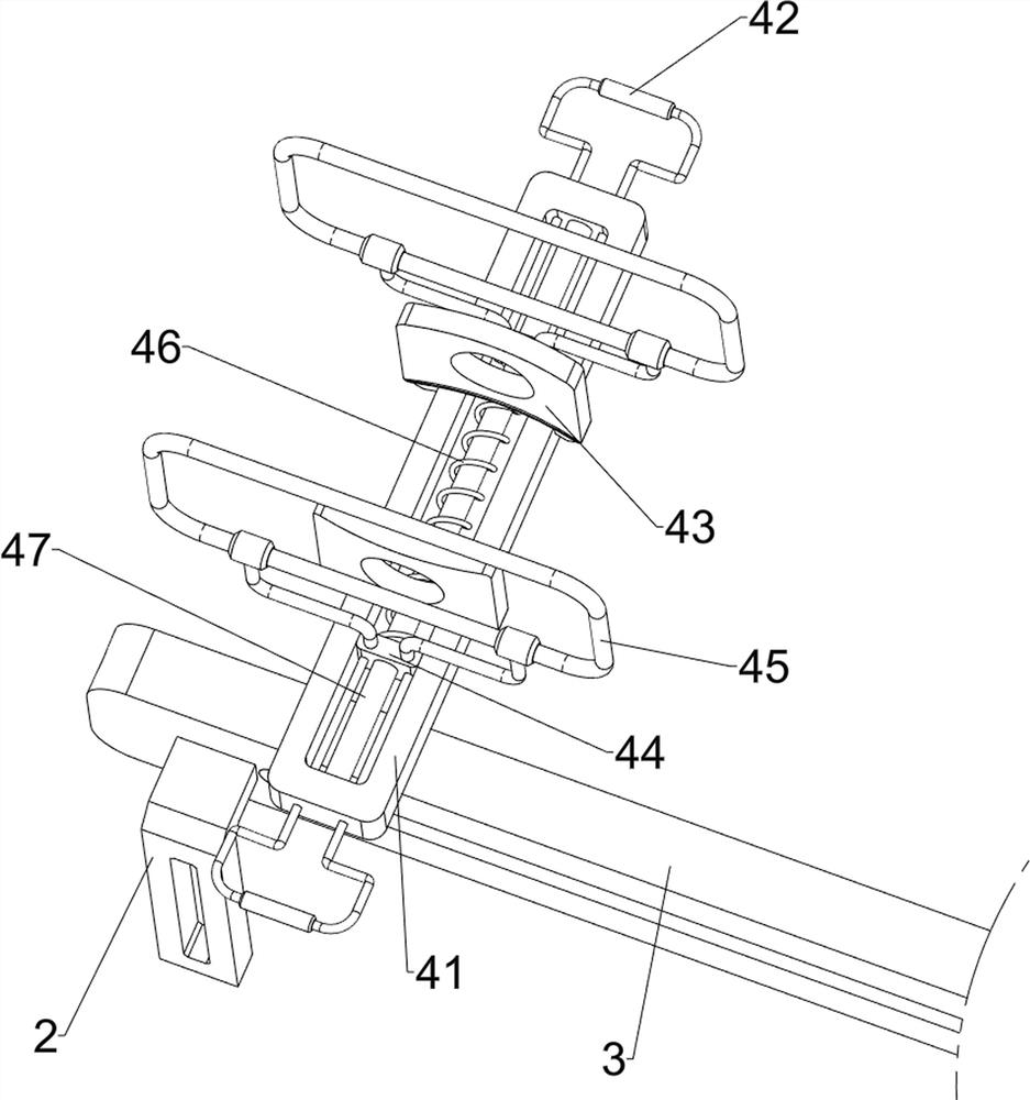
[0086] On the basis of Example 1, such as Figure 2-Figure 5 As shown, the clamping mechanism 4 includes a first fixed frame 41, a handle 42, a first baffle plate 43, a sliding block 44, a clamp 45, a first spring 46 and a guide column 47, and a sliding arrangement is arranged between the guide rails 3 on both sides. There is a first fixed frame 41, a first baffle plate 43 is arranged symmetrically in the middle of the upper side of the first fixed frame 41, and a guide column 47 is arranged between the front and rear sides of the upper inner wall of the first fixed frame 41, and the front and rear sides of the guide column 47 all slide A sliding block 44 is arranged in the formula, and handles 42 are symmetrically arranged on the outer sides of the two sliding blocks 44, and the handle 42 is slidably connected with the first fixed frame 41. The tops of the sliding blocks 44 on both sides are provided with clamps 45, and the middle of the guide column 47 is wound with a The fi...
Embodiment 3
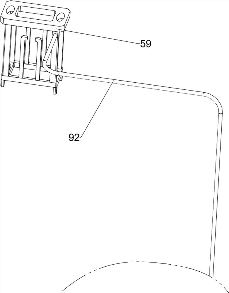
[0093] On the basis of Example 2, such as Figure 6-Figure 10 Shown, also comprise rotating mechanism 7, and rotating mechanism 7 comprises the 3rd bracket 71, the first tooth rack 72, the first rotating shaft 73, the first one-way gear 74, belt transmission group 75, the second rotating shaft 76, convex Block 77 and the fourth support 78, the third support 71 is arranged between the left and right sides in the middle of the third fixed frame 59 bottom, the second support 61 upper right rear part is provided with the first tooth bar 72, the third fixed frame 59 under The left and right sides of the side are all symmetrically provided with a fourth support 78, and the first rotating shaft 73 is rotationally provided between the four fourth support 78 upper side inner walls, and the first one-way gear 74 is arranged in the middle of the first rotating shaft 73. The gear 74 meshes with the first rack 72, and the third support 71 lower side is rotatably provided with a second rota...
PUM
 Abstract
Description
Claims
Application Information
 - R&D
- Intellectual Property
- Life Sciences
- Materials
- Tech Scout
- Unparalleled Data Quality
- Higher Quality Content
- 60% Fewer Hallucinations
Browse by: Latest US Patents, China's latest patents, Technical Efficacy Thesaurus, Application Domain, Technology Topic, Popular Technical Reports.
© 2025 PatSnap. All rights reserved.Legal|Privacy policy|Modern Slavery Act Transparency Statement|Sitemap|About US| Contact US: help@patsnap.com


