Equipment state information normalization acquisition method

A technology of equipment status and collection method, applied in the direction of comprehensive factory control, instruments, and comprehensive factory control, etc., can solve the problems of difficult to accurately describe, difficult to realize status collection, increase the workload of software development, etc., to achieve easy monitoring and convenient unified supervision Effect

Active Publication Date: 2021-08-20
ZHEJIANG UNIV CITY COLLEGE
View PDF4 Cites 0 Cited by
  • Summary
  • Abstract
  • Description
  • Claims
  • Application Information

AI Technical Summary

Problems solved by technology

[0009] In this case, it is difficult for the conventional state acquisition module to realize the state acquisition of the device, because when the device is running normally, the collected "0" or "1" will be sent to the application software alternately, and the application software will display The device switches between "stop" and "failure", which is difficult to describe accurately
In addition, when there are multiple devices to be managed, the running status of different devices is different, for example: device A defines "1" as the running state, while device B defines "0" as the running state, when two devices When both are running, one is "1" and the other is "0" to the upper application software using the conventional state acquisition module, so it is difficult to give a unified state value for different devices, and the application software needs to send values ​​to different devices It is processed separately, and specific processing is required for the state values ​​of different devices. To add new devices or adjust the device status in the later stage, it is necessary to modify the software to cooperate with them, which increases the workload of software development, and is not easy to design and maintain software modularization. Increased software development workload

Method used


Image

  • Equipment state information normalization acquisition method
  • Equipment state information normalization acquisition method
  • Equipment state information normalization acquisition method

Examples


Embodiment

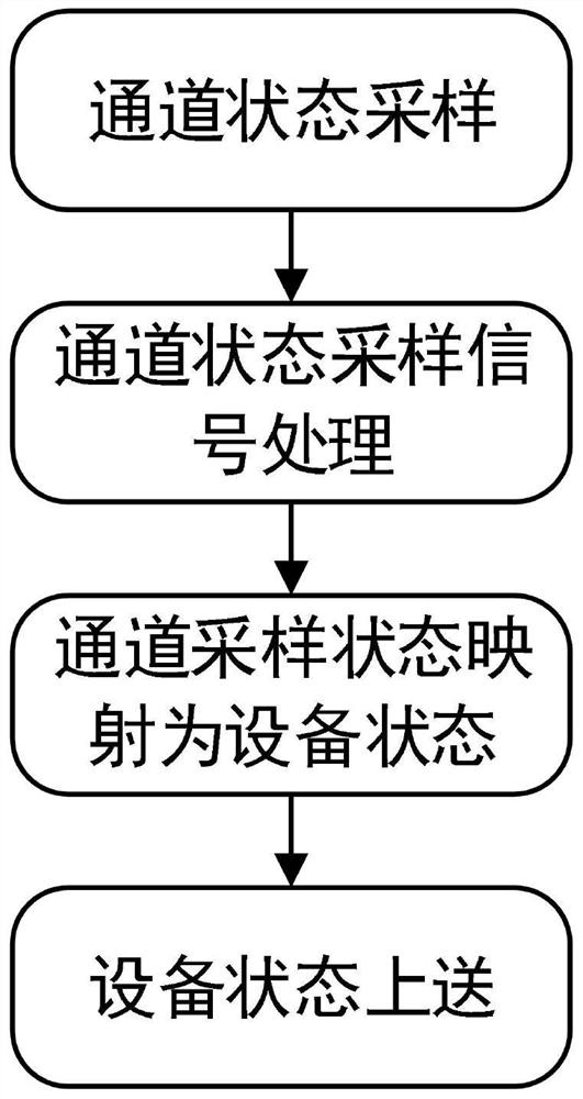
[0026] Embodiment: a method for normalized collection of equipment state information, such as figure 1 shown, including the following steps:

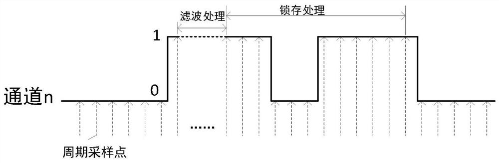
[0027] S1: if figure 2 As shown, the MCU (microcontroller, single-chip microcomputer) periodically collects the state signal of the channel input, that is, collects the state signal of the channel input at an interval of t, and the state signal includes the first signal and the second signal, such as figure 2 The first signal shown in is a "0" signal, and the second signal is a "1" signal.

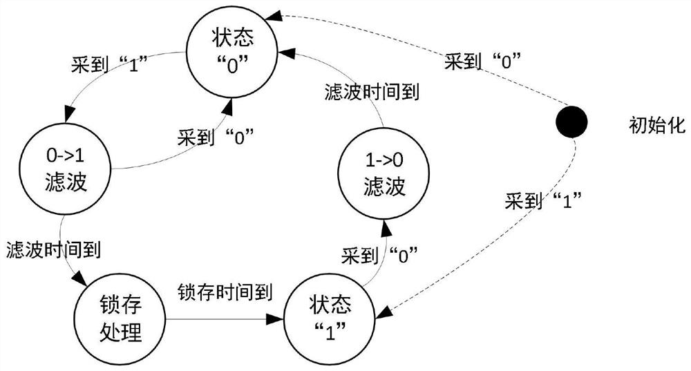
[0028] S2: Initialize the state signal of MUC acquisition channel input, take the first signal as the first state to collect the state signal, take the second signal as the second state as the second signal with the state signal collected; image 3 As shown, the first state is the state "0", and the second state is the state "1". When the "0" signal is collected, it enters the state "0", and when the "1" signal is collected, the state is "1". ....


PUM


Abstract

The invention discloses an equipment state information normalization acquisition method, which comprises the following steps: S1, an MCU periodically collects state signals input by a channel, and the state signals comprise a first signal and a second signal; S2, state signals collected by the MCU input by the channel are initialized, a first signal of the acquired state signals is taken as a first state, and a second signal of the acquired state signal is taken as a second state; S3, in the first state, when the state signal collected by the MCU is changed from the first signal to the second signal, filtering is carried out, latching is carried out after filtering processing, and when latching is finished, a second state is entered, and sampling is completed; and S4, a mapping table is set, a corresponding mapping value in the mapping table is obtained according to sampling in the step S2, and the mapping value is uploaded to complete normalized acquisition of the state information. According to the invention, the state information of the equipment is subjected to normalized acquisition, and unified supervision of the equipment is facilitated.

Description

technical field [0001] The invention relates to the technical field of using digital processing, in particular to a method for normalized collection of equipment status information. Background technique [0002] Due to the requirements of intelligent production and fine management, enterprises need to obtain the real-time operation status of equipment during the production process, which helps to improve the enterprise's visual management of the production process, optimal production scheduling design, energy efficiency management, etc. [0003] In industrial production activities, different equipment will be involved in collaborative production, and the operating status of each production equipment has its own definition. Generally, the equipment will use tower lights (a group of combined lights of different colors) to indicate the current operating status of the equipment itself (such as: normal operation, standby, stop, failure, etc.), but the form of indication and the c...

Claims


Application Information

Patent Timeline
IPC IPC(8): G05B19/418
CPCG05B19/4184G05B2219/31088Y02P90/02
Inventor 俞雯
Owner ZHEJIANG UNIV CITY COLLEGE
Why Eureka
Try Eureka