Image correction method and shooting equipment

A technology for photographing equipment and image correction, applied in the field of projection display, can solve problems such as poor display effect of projected images, and achieve the effects of ensuring display effect, ensuring reliability, and improving reliability

Pending Publication Date: 2021-08-20
QINGDAO HISENSE LASER DISPLAY CO LTD
View PDF0 Cites 1 Cited by
  • Summary
  • Abstract
  • Description
  • Claims
  • Application Information

AI Technical Summary

Problems solved by technology

[0003] The embodiment of the present disclosure provides an image correction method, which can solve the problem in the related art that the projected image d

Method used


Image

  • Image correction method and shooting equipment
  • Image correction method and shooting equipment
  • Image correction method and shooting equipment

Examples


Example Embodiment

[0050] In order to make the objects, technical solutions and advantages of the present disclosure, the present disclosure will be further described in detail below with reference to the accompanying drawings.

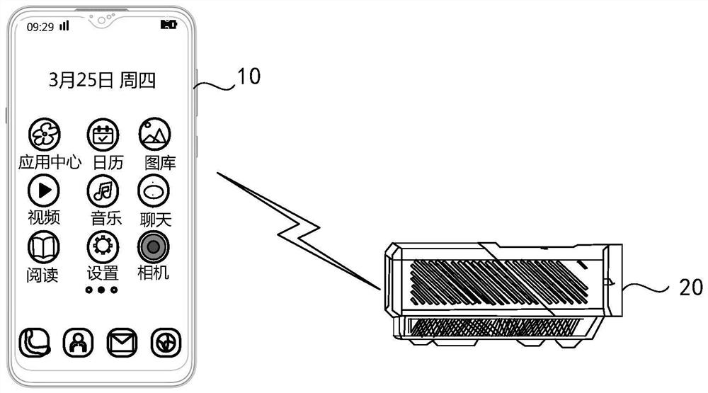
[0051] figure 1 It is an implementation environment involved in an image correction method according to an embodiment of the present disclosure. like figure 1 As shown, the implementation environment may include: photographing device 10 and laser projection device 20.

[0052] Wherein, the photographing device 10 can be a device configured with a camera, for example, a device that is a mobile phone, a personal computer, a laptop, or a tablet, or the like. The laser projection device 20 can be an ultra short-focus laser projection device. The photographing device 10 can be connected to the laser projection device 20 through a wired network or a wireless network.

[0053] figure 2 It is a flow chart of an image correction method provided by the embodiment of the present dis...


PUM


Abstract

The invention discloses an image correction method and shooting equipment, and belongs to the field of projection display. According to the method, after a shot image obtained by shooting a projection screen is obtained, the shot image can be sent to laser projection equipment. Therefore, the laser projection equipment corrects the projection position of the projection image to be displayed based on the shot image, thereby ensuring the display effect of the projection image. Moreover, if the shooting equipment detects that the frame of the projection screen in the preview picture is located outside the target area of the preview picture, the adjustment prompt information can be displayed. In this way, a user can adjust the shooting parameters of the camera in time, it is ensured that the shot image collected by the camera meets the requirement, the reliability of the collected shot image is ensured, and then the reliability of correcting the projection position of the projection image to be displayed based on the shot image is improved.

Description

technical field [0001] The present disclosure relates to the field of projection display, in particular to an image correction method and a shooting device. Background technique [0002] Ultra-short-throw laser projection equipment can project and display projected images on a projection screen. For ultra-short-focus laser projection equipment, due to the principle of projection imaging, the light is emitted obliquely upwards, so the position between the laser beam emitted by the optical engine in the ultra-short-focus laser projection equipment and the projection screen must be strictly aligned. A slight shift of the focal laser projection equipment can also cause distortion or distortion of the picture. If the user accidentally moves the ultra-short-focus laser projection device, the projected image projected and displayed by the ultra-short-focus laser projection device may exceed the projection screen, resulting in a poor display effect of the displayed projected image....

Claims


Application Information

Patent Timeline
IPC IPC(8): H04N9/31H04N5/232H04N17/00
CPCH04N9/3161H04N9/3185H04N17/00H04N23/632
Inventor 陈许张冬冬
Owner QINGDAO HISENSE LASER DISPLAY CO LTD
Why Eureka
Try Eureka