
Tongue depressor for department of pediatrics

A tongue depressor and pediatric technology, applied in the field of medical devices, can solve the problems of increasing the difficulty of work, blocking the line of sight, time-consuming and laborious, etc., and achieving the effects of saving manpower and material resources, improving work efficiency, and expanding vision

Active Publication Date: 2021-08-24
罗瑶
View PDF9 Cites 0 Cited by
  • Summary
  • Abstract
  • Description
  • Claims
  • Application Information

AI Technical Summary

Problems solved by technology

[0002]Clinically, when checking the throat of a patient, most patients use a spatula to press the tongue to observe the lesions in the throat. The existing spatula is straight, so The operation of pressing the tongue is very troublesome, time-consuming and laborious, and the doctor's hand will block the line of sight during the examination, so that a comprehensive examination cannot be performed; especially when examining some children, many children are unwilling to cooperate and often close their mouths by themselves during the examination. The tongue depressor is easy to fall off because of the mouth and teeth, which not only cannot be checked well but also increases the difficulty of work for the medical staff, especially when it is necessary to check and diagnose the deep throat of children, it is very inconvenient; and the existing The tongue depressor requires the patient to forcefully open the mouth when using it, which is a difficult action for children with tonsillitis
And when the child is examined, the saliva in the mouth cannot be discharged in time, which makes the child feel uncomfortable.

Method used


Image

  • Tongue depressor for department of pediatrics
  • Tongue depressor for department of pediatrics
  • Tongue depressor for department of pediatrics

Examples


Embodiment Construction

[0042] For ease of understanding, the technical solutions of the present invention are further specifically described below in conjunction with the accompanying drawings and through embodiments:

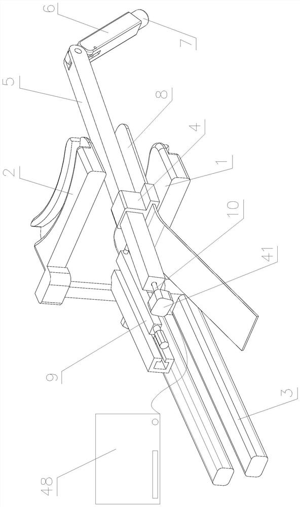
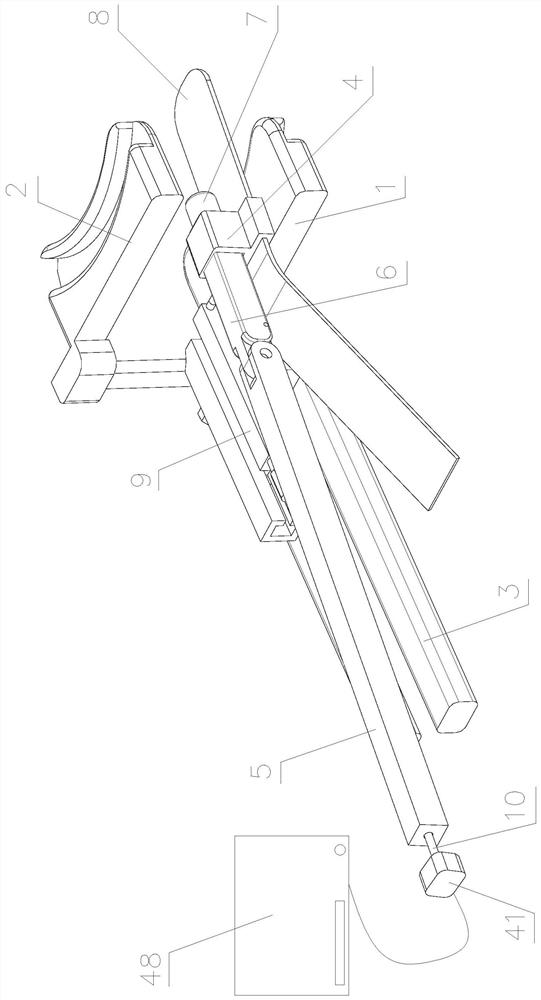
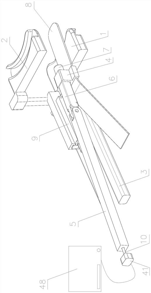
[0043] Such as Figure 1-Figure 13 As shown, a tongue depressor for pediatrics includes a lower dental clamp assembly 1, an upper dental clamp assembly 2, a pull rod 3, a swivel seat 4, a sliding rod 5, a rotary rod 6, a camera 7, a tongue depressor 8, a sliding Bracket 9 and display screen 48.

[0044] The upper tooth clip assembly 2 is vertically slidably arranged on the lower tooth clip assembly 1 .

[0045] The pull rod 3 is detachably arranged at the lower end of the clamping plate assembly 2 of the upper teeth.

[0046] The sliding bracket 9 is provided on the lower dental card plate assembly 1 so as to slide in parallel.

[0047] The swivel base 4 is rotatably arranged on the sliding bracket 9 .

[0048] The slide bar 5 is slidably arranged on the swivel base 4 .

[0049]...


PUM


Abstract

A tongue depressor for the department of pediatrics comprises a lower tooth clamping plate assembly, an upper tooth clamping plate assembly, a pull rod, a tongue depressor, a sliding bracket and a display screen. The upper tooth clamping plate assembly is arranged on the lower tooth clamping plate assembly in a vertically sliding mode. The pull rod is detachably arranged at the lower end of the upper tooth clamping plate assembly. The sliding bracket is arranged on the lower tooth clamping plate assembly in a parallel sliding mode. A rotating seat is rotatably arranged on the sliding bracket. And the tongue depressor is arranged on the rotating seat in a sliding manner. A sliding rod is arranged on the rotating seat in a sliding manner. A rotating rod is rotatably arranged at the front end of the sliding rod. A camera is arranged at the front end of the rotating rod. The camera is connected with the display screen through a wire. According to the invention, the teeth of a child patient can be expanded to a proper position and are locked and positioned, so that inconvenience in examination due to the fact that the child closes the mouth and the teeth by himself during examination is prevented; The oral and intra-laryngeal visual fields can be expanded, working efficiency is improved, and manpower and material resources are saved.

Description

technical field [0001] The invention belongs to the technical field of medical devices, and in particular relates to a pediatric tongue depressor. Background technique [0002] Clinically, when checking the throat of a patient, most of them use a spatula to press the tongue to observe the lesions in the throat. The existing spatula is in the shape of a straight plate, so the operation of pressing the tongue is very troublesome, time-consuming and laborious. Hands will block the line of sight, so that a comprehensive inspection cannot be performed; especially when inspecting some children, many children are unwilling to cooperate and often forcefully close their mouths and teeth during the inspection, causing the tongue depressor to fall off easily. Very good inspection and good work difficulty for medical staff, especially when it is necessary to check and diagnose the deep throat of children, it is very inconvenient; and the existing tongue depressor requires the patient to...

Claims


Application Information

Patent Timeline
IPC IPC(8): A61B1/247A61B13/00
CPCA61B1/247A61B13/00
Inventor 罗瑶李玲刘俊燕
Owner 罗瑶
Learn More