
A dynamic adjustment system and construction method for main cable lateral movement of suspension bridge

A technology for dynamic adjustment and suspension bridges, applied in suspension bridges, bridges, bridge construction, etc., can solve problems such as poor stability, achieve good stability, ensure safety, and improve ductility

Active Publication Date: 2022-05-27
CHANGAN UNIV
View PDF0 Cites 0 Cited by
  • Summary
  • Abstract
  • Description
  • Claims
  • Application Information

AI Technical Summary

Problems solved by technology

[0005] Aiming at the deficiencies in the prior art, the object of the present invention is to provide a dynamic adjustment system for the lateral movement of the main cable of the suspension bridge and its construction method, so as to solve the problems of the cable used for the lateral movement of the main cable during the conversion of the suspension bridge system in the prior art. The technical problem of poor stability of the temporary fixed support device between

Method used


Image

  • A dynamic adjustment system and construction method for main cable lateral movement of suspension bridge
  • A dynamic adjustment system and construction method for main cable lateral movement of suspension bridge
  • A dynamic adjustment system and construction method for main cable lateral movement of suspension bridge

Examples


Embodiment 1

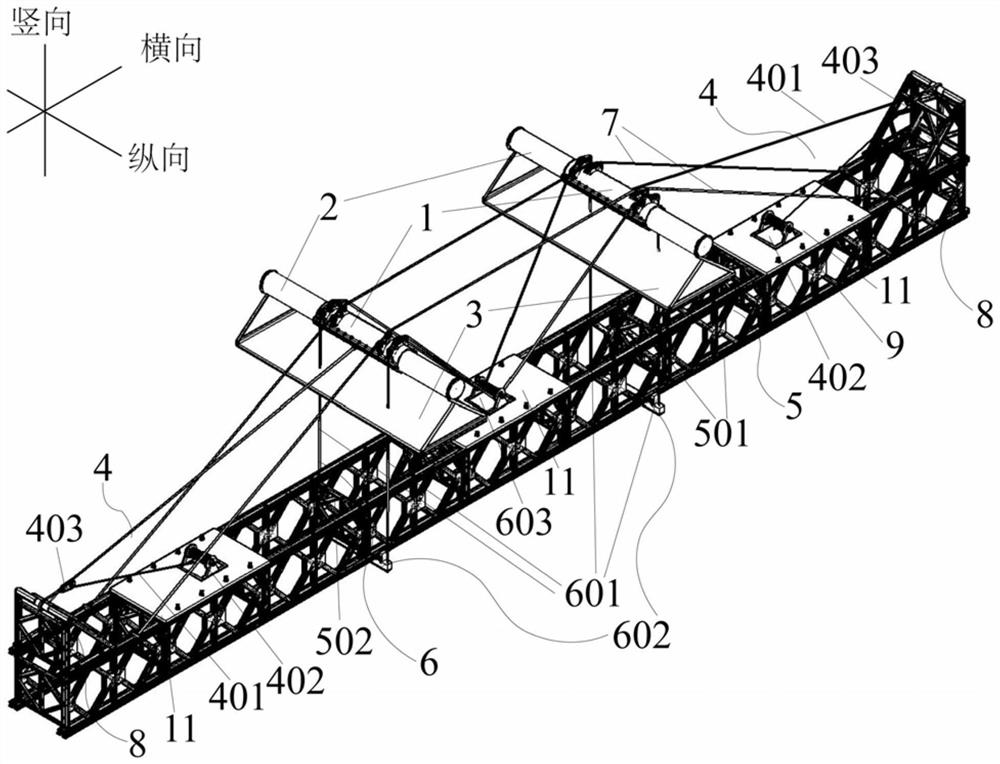
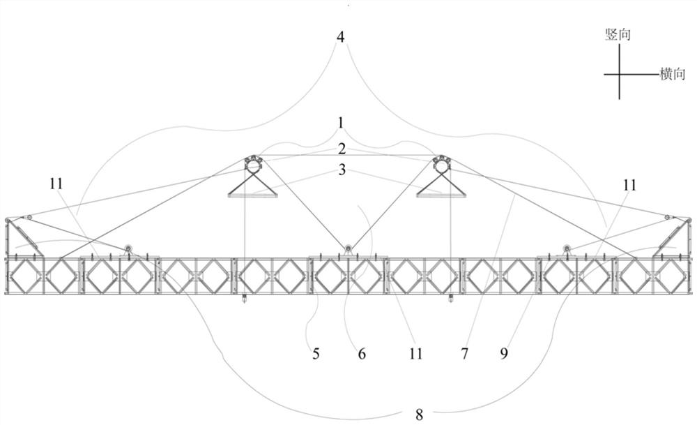
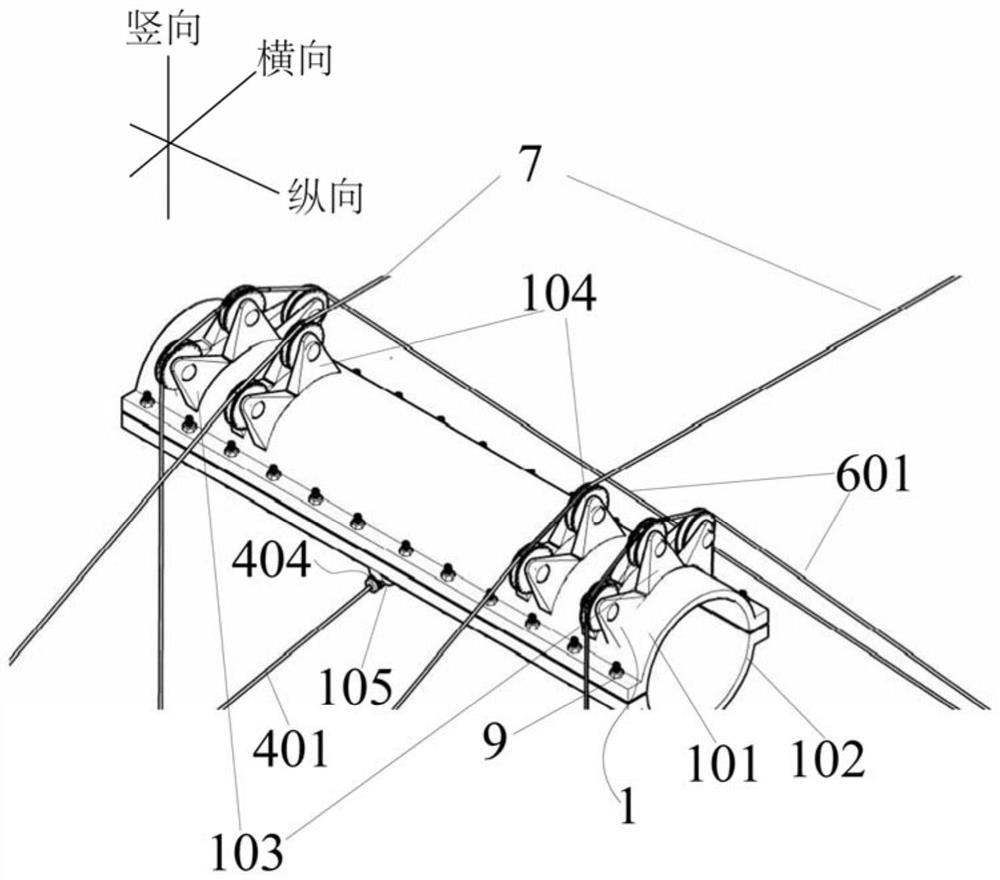
[0063] This embodiment provides a dynamic adjustment system for the lateral movement of the main cable of a suspension bridge, such as Figure 1 to Figure 10 As shown, a pair of main cable holding clips 1 are included, and a pair of main cable holding clips 1 are respectively arranged on a pair of main cables 2 in parallel and longitudinally opposite to each other, and a catwalk 3 is connected below the main cable 2; A transverse tensioning device 4 is fixedly installed on the upper surface, which is characterized in that a pair of transverse tensioning devices 4 are relatively fixedly installed on the top of the Bailey beam 5, and the Bailey beam 5 is located below the catwalk 3; the main cable 2 can be horizontally The lateral movement is carried out under the traction of the tensioning device 4;

[0064] A vertical support device 6 is arranged between a pair of lateral tensioning devices 4, and the vertical support device 6 is fixedly installed on the Bailey beam 5 and is a...

Embodiment 2

[0084] This embodiment provides a dynamic adjustment construction method. In this embodiment, the method adopts the dynamic adjustment system for the lateral movement of the main cable of the suspension bridge in Embodiment 1, and the method includes the following specific steps:

[0085] Step 1, Design and Assemble the Bailey Beam:

[0086] Design the length of the Bailey beam 5 according to the final linear shape required by the main cable 2 of the suspension bridge, assemble the designed Bailey beam 5, then fix the steel plate 11 on the top of the Bailey beam 5, and install the steel plate 11 on the top of the Bailey beam 5. A vertical support cable fixing part 602 is fixedly installed on the bottom end of the cable.

[0087] In this embodiment, the specific steps for installing the vertical support cable fixing portion 602 are: firstly install the roller 60203- in the roller bracket 60204, and then weld the inverted L-shaped blocks on the longitudinal ends of the upper sur...


PUM


Abstract

The invention provides a dynamic adjustment system for the lateral movement of the main cable of a suspension bridge and a construction method thereof. A horizontal tensioning device is fixedly installed, and a pair of horizontal tensioning devices are relatively fixedly installed on the top of the Bailey beam. The Bailey beam is located below the catwalk, and the main cable can move laterally under the traction of the horizontal tensioning device; one A vertical support device is arranged between the horizontal tensioning devices, the vertical support device is arranged on the main cable holding clip, and the main cable holding clip is also provided with an auxiliary load-bearing cable; in the present invention, the weight of the Bailey beam is determined by the horizontal The tensioning device, the vertical support device and the auxiliary load-bearing cables are jointly borne by the three. Under the influence of lateral unbalanced force and wind load, the dynamic adjustment system of the present invention can still maintain good stability and strong adaptability. Thereby ensuring the safety of construction.

Description

technical field [0001] The invention belongs to the technical field of suspension bridge construction, relates to suspension bridge system conversion, and in particular relates to a dynamic adjustment system for lateral movement of main cables of a suspension bridge and a construction method thereof. Background technique [0002] Different from the traditional plane cable suspension bridge, the surface formed by the main cable and the suspension cable of the space cable suspension bridge is a space curved surface, the main cable suspension cable is no longer a vertical plane but a horizontally inclined plane, that is, the main cable not only has vertical The lateral sag and also the lateral sag lead to a great difference between the lateral coordinates of the space cable suspension bridge in the empty cable stage and the bridge stage. The difficulty is high. In the actual construction process, the sling cannot be installed because the sling lug cannot be inserted into the ca...

Claims


Application Information

Patent Timeline
Patent Type & Authority Patents(China)
IPC IPC(8): E01D19/00E01D11/02E01D19/16E01D21/00
CPCE01D19/00E01D11/02E01D19/16E01D21/00
Inventor 王晓明白云腾黄春杨王炳玉邹杰张嘉鼎录哲元
Owner CHANGAN UNIV
Learn More