Ceramic tile laying structure and laying method thereof

A ceramic tile and the same technology, applied to the ceramic tile laying structure and the laying field, can solve the problems of waiting for the cement mortar to solidify, the laying process is cumbersome, etc., and achieve the effects of improving the laying efficiency, rapid erection, and improved applicability

Inactive Publication Date: 2021-08-24
变形积木(北京)科技有限公司
View PDF0 Cites 5 Cited by
  • Summary
  • Abstract
  • Description
  • Claims
  • Application Information

AI Technical Summary

Problems solved by technology

[0003] The existing tiles need to be cleaned first when laying. Before laying, the walls around the space should be leveled horizontally, and vertical lines should be made at appropriate positions so as to determine the size of the floor tiles out of the wall, and then determine the horizontal line. When laying tiles, use a shovel to evenly apply cement mortar on the back of the tiles, gently lay the tiles on the ground floor, and use a rubber hammer to gently beat the tiles so that the tiles are on the same level. During the laying process, laying personnel are required Control the amount of cement mortar used on each tile, and at the same time need to adjust the position of each tile one by one. After the laying is completed, it is necessary to wait for the cement mortar to solidify. The laying process is cumbersome

Method used


Image

  • Ceramic tile laying structure and laying method thereof
  • Ceramic tile laying structure and laying method thereof
  • Ceramic tile laying structure and laying method thereof

Examples


Embodiment Construction

[0041] The following is attached Figure 1-5 The application is described in further detail.

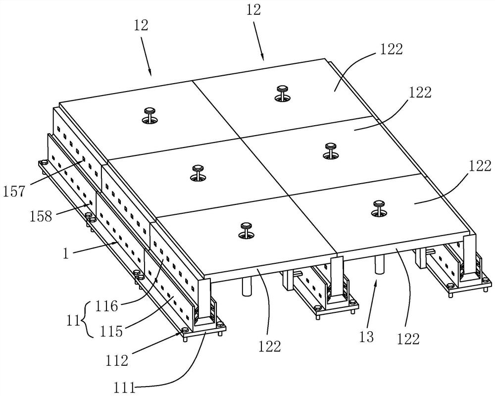
[0042] The embodiment of the present application discloses a ceramic tile laying structure. refer to figure 1 , a tile laying structure, comprising a plurality of fixed bars 1 spaced apart from each other and arranged in parallel, each fixed bar 1 includes a plurality of connecting bars 11 located on the same straight line, the bottom of each connecting bar 11 is along the connecting bar 11 A mounting plate 111 is provided in the lengthwise direction of the mounting plate 111 for abutting against the ground base, and a plurality of mounting holes 112 for bolts to pass through are opened on the mounting plate 111.

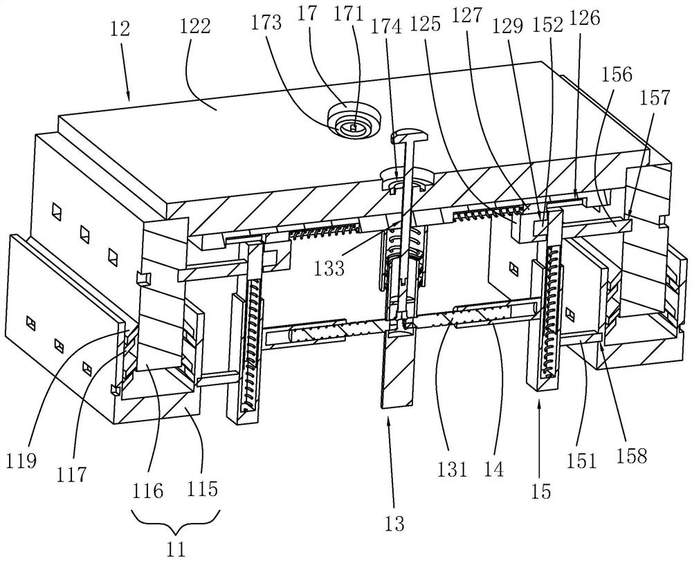
[0043] combine figure 1 with figure 2 , a decorative board 12 is placed between every two adjacent fixing strips 1, in order to drive the adjacent decorative boards 12 to abut together, there are holes on both sides of each decorative board 12 for the fixing strip 1 t...


PUM


Abstract

The invention relates to a ceramic tile laying structure. The ceramic tile laying structure comprises a plurality of fixing strips, each fixing strip comprises a plurality of connecting strips, a decorative plate is placed between every two adjacent fixing strips, each decorative plate comprises a plurality of ceramic tile plates, the back face of each ceramic tile plate is detachably connected to a connecting plate, a supporting rod is fixedly arranged in the middle of each connecting plate, and the end, away from the corresponding connecting plate, of each supporting rod is used for being supported on a ground base layer; connecting rods are arranged on the two sides of each supporting rod, a mounting rod is arranged at the end, away from the corresponding supporting rod, of each connecting rod, a first mounting block is arranged on each mounting rod, and a first mounting groove is formed in each connecting strip; and each supporting rod is provided with a driving mechanism used for simultaneously driving the connecting rods on the two sides so as to drive the first mounting block to move into or out of the corresponding first mounting groove. The ceramic tile laying structure and the laying method thereof have the advantages that ceramic tiles can be conveniently erected, and the ceramic tile erecting efficiency can be improved.

Description

technical field [0001] The present application relates to the field of prefabricated decoration, in particular to a tile laying structure and a laying method thereof. Background technique [0002] As one of the main materials for interior decoration, tiles are favored by people for their various types and colors, as well as different collocations and applications. [0003] The existing tiles need to be cleaned first when laying. Before laying, the walls around the space should be leveled horizontally, and vertical lines should be made at appropriate positions so as to determine the size of the floor tiles out of the wall, and then determine the horizontal line. When laying tiles, use a shovel to evenly apply cement mortar on the back of the tiles, gently lay the tiles on the ground floor, and use a rubber hammer to gently beat the tiles so that the tiles are on the same level. During the laying process, laying personnel are required Control the amount of cement mortar used ...

Claims


Application Information

Patent Timeline
Patent Type & Authority Applications(China)
IPC IPC(8): E04F15/02E04F13/08E04F13/21E04F21/22E04F21/18
CPCE04F13/08E04F13/0801E04F15/02E04F15/02044E04F21/1844E04F21/22
Inventor 杨秀召张轶然王子诚
Owner 变形积木(北京)科技有限公司
Why Eureka
Try Eureka